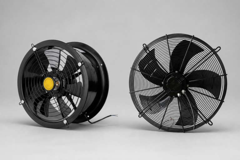
How to Choose a Small Axial Fan for Equipment Cooling
Published: Author: Rachel
A small axial fan is often the simplest way to remove heat from a control cabinet, power supply, automation device, telecom enclosure, or compact machine. However, the fan with the highest free-air CFM is not automatically the best choice. Real cooling performance depends on the heat load, permitted temperature rise, airflow resistance, voltage, frame size, noise limit, bearing system, operating environment, and installation layout.
For B2B buyers, model selection must also consider supply continuity, dimensional consistency, electrical connections, performance documentation, sample testing, and customization requirements. This guide explains how to choose a small axial fan for an industrial or commercial equipment project without relying on frame size or headline airflow alone.
After defining the required airflow, voltage, size, and working environment, buyers can compare Yian Electric’s small axial fan range.
What Is a Small Axial Fan?
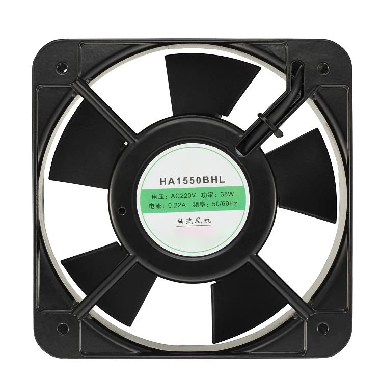
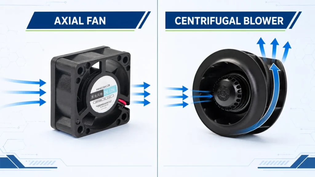
A small axial fan moves air in a direction roughly parallel to the fan shaft. The motor turns an impeller inside a compact square or round frame, drawing air through one side and discharging it through the other.
Compared with a centrifugal blower, a compact axial fan normally provides a direct airflow path and a space-efficient mounting format. It is commonly used for:
electrical and control cabinet ventilation;
power supply and inverter cooling;
PLC, drive, and automation equipment;
telecom and network enclosures;
test instruments and commercial equipment;
machine control boxes and compact electronic assemblies.
Small axial fans are available with AC or DC input, multiple frame sizes, different airflow and noise levels, and several bearing or control options. The product must be matched to the installed system, not selected from appearance alone.
When Is a Small Axial Fan the Right Choice?
An axial fan is a strong starting point when the air can move through a short, reasonably open path. It works well when the objective is to exchange warm enclosure air with cooler ambient air or to move air directly across heat-generating components.
If the air must pass through a dense filter, restrictive heat exchanger, long duct, narrow outlet, or tightly packed internal channel, system resistance may become the dominant requirement. A centrifugal blower or another higher-pressure solution may then perform better.
Air-system condition
Better starting point
Reason
Open intake and exhaust, short airflow path
Small axial fan
Efficient direct airflow in a compact frame
Control cabinet with moderate component density
Small axial fan after checking the fan curve
Airflow can be sufficient if vents and filters are sized correctly
Dense fins, restrictive filter, or narrow internal channel
Compare axial fan with a centrifugal blower
Static-pressure capability becomes more important
Air must turn sharply or exit through a directed outlet
Small centrifugal blower
Scroll housing produces directional airflow
Localized cooling across a board or power module
Small axial fan or blower, depending on resistance
Geometry and operating point determine the better choice
The final decision should be based on the airflow–static pressure curve and an installed test.
How to Choose a Small Axial Fan Step by Step
1. Define the heat load and temperature limit
Begin with the equipment, not the fan catalog. Record:
total internal heat generation in watts;
maximum expected ambient temperature;
maximum permitted internal temperature;
target temperature rise above ambient;
operating hours and duty cycle;
location of the main heat sources.
Use power loss rather than total equipment input power whenever possible. A 1 kW power supply does not necessarily release 1 kW as heat; the thermal load is the power lost inside the enclosure. Obtain loss data from the equipment or component manufacturer.
If several devices produce heat, add their maximum simultaneous losses. Include a reasonable engineering margin for operating variation, component tolerance, dust accumulation, and future configuration changes.
2. Estimate the required airflow
For an early forced-air estimate, ventilation airflow can be approximated from heat load and allowable temperature rise:
Q ≈ P ÷ (20 × ΔT)
Where:
Q = estimated ventilation airflow in m³/min;
P = internal heat load in watts;
ΔT = permitted temperature rise in kelvin or degrees Celsius.
Example: if the internal heat load is 150 W and the target temperature rise is 10°C:
Q ≈ 150 ÷ (20 × 10) = 0.75 m³/min, or approximately 26.5 CFM.
This is a starting estimate, not a guaranteed fan duty point. It assumes simplified air properties and does not include the pressure loss created by internal components, vents, filters, grilles, or ducting. Use thermal simulation or prototype measurements when overheating would create a safety, reliability, or warranty risk.
3. Check static pressure and the operating point
Fan datasheets commonly show maximum airflow and maximum static pressure. These two maximum values do not occur simultaneously.
Maximum airflow is measured near a free-air condition with very little resistance.
Maximum static pressure occurs near zero airflow.
The installed operating point is where the fan’s performance curve intersects the system-resistance curve.
As resistance increases, delivered airflow falls. Common sources of pressure loss include:
dust filters;
protective grilles and guards;
small intake or exhaust openings;
densely installed components;
heat sinks and coils;
bends, partitions, and cable bundles;
long or narrow airflow passages.
When comparing models, request the full airflow–static pressure curve rather than selecting only by maximum CFM. If the supplier does not provide a curve, prototype testing becomes even more important.
Improving the enclosure can sometimes be more effective than choosing a faster fan. Increase outlet area, move cables away from the flow path, separate hot and cool air, and position the fan so that fresh air passes over the hottest components before leaving the enclosure.
4. Choose AC or DC power
Match the fan to the power already available in the equipment.
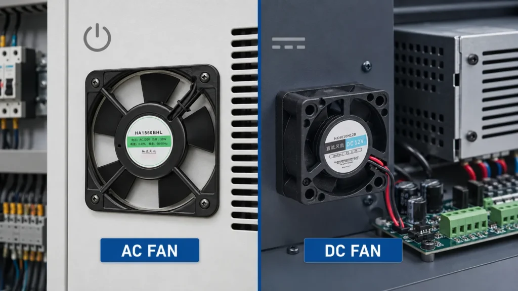
A small AC fan can connect to the specified AC supply and is often used in control cabinets, commercial equipment, and industrial enclosures. Confirm voltage and frequency because performance may change between 50 Hz and 60 Hz.
A small DC fan suits equipment with an existing low-voltage DC bus. DC models can also support functions such as speed control, tachometer feedback, locked-rotor protection, or alarm output when those functions are designed into the fan.
Do not assume that all AC or DC models include the same protection and control features. Confirm each function in the exact model datasheet.
A fan that fits the front opening may still interfere with a PCB, terminal block, door, cable duct, or protective grille. For an OEM replacement project, compare the complete drawing rather than relying on a label such as “80 mm fan.”
Avoid placing a major obstruction immediately against the inlet. A smooth intake and a clear exhaust path reduce turbulence, airflow loss, and unnecessary noise. Use arrows on the housing or the manufacturer’s drawing to confirm the airflow direction.
6. Compare airflow, static pressure, noise, speed, power, and bearing
Use the following parameters together:
Specification
What it tells you
Selection caution
Airflow, CFM or m³/h
Air volume under the stated test condition
Free-air airflow is not the installed airflow
Static pressure, Pa or mmH₂O
Ability to overcome resistance
Check the full curve at the required flow
Speed, RPM
Impeller rotational speed
Higher speed can increase airflow, pressure, noise, and wear
Noise, dB(A)
Sound pressure under stated conditions
Compare measurement distance and test conditions
Input power/current
Electrical load on the supply
Check startup current and supply capacity where applicable
Bearing type
Mechanical support and lubrication design
Confirm life at the real temperature, duty, and orientation
Life expectancy
Test-based durability reference
Compare temperature and test definition, not hours alone
For continuous industrial operation, request life data at the expected ambient temperature. A lifetime value at 25°C cannot automatically be applied to a hot cabinet. Also decide whether lower noise, longer maintenance intervals, lower power consumption, or lower purchase cost has the highest project priority.
7. Check environment, protection, and control functions
The fan’s operating environment can change both cooling performance and service life. Confirm:
minimum and maximum temperature;
humidity and condensation risk;
dust, oil mist, salt, and corrosive gas;
water exposure and required IP protection;
shock and vibration;
altitude and air-density conditions where relevant;
indoor or outdoor installation;
applicable product safety and material requirements.
If a fan is installed with a filter, establish a cleaning or replacement interval. A loaded filter increases resistance and reduces airflow. For critical systems, consider a temperature alarm, tachometer signal, locked-rotor output, redundancy, or preventive replacement schedule.
Ask the supplier which monitoring or control functions are standard, optional, or unavailable. Do not write them into the equipment specification until they are confirmed for the exact model.
AC vs DC Small Axial Fan
Selection factor
Small AC fan
Small DC fan
Power source
AC line supply at the specified voltage/frequency
Low-voltage DC supply
Typical use
Control cabinets, industrial enclosures, commercial equipment
Electronics, automation modules, power supplies, telecom, compact devices
Speed control
Depends on motor and model; verify method
May support voltage or PWM control, depending on model
Monitoring
Model-dependent
Tachometer, alarm, or locked-rotor signal may be available
Wiring
Line/neutral and protective earth where required
Polarity, connector, and signal wires must be checked
Global sourcing concern
Confirm 50/60 Hz and regional line voltage
Confirm DC rail, voltage tolerance, current, and connector pinout
Best selection basis
Available AC supply plus fan curve and environment
Available DC rail plus fan curve, control needs, and environment
Neither type is universally better. Choose the fan that fits the equipment’s electrical architecture, thermal duty, control requirements, and service environment.
What is the maximum ambient temperature and maintenance interval?
Commercial equipment
Noise, safety, cleaning, supply voltage
Will the fan operate near customers or staff?
Distributor inventory
Common sizes, voltage options, documentation, packaging
Which models cover the largest share of customer applications?
For wholesalers and distributors, stocking only by frame size can create gaps. A practical range should also cover supply voltage, airflow class, bearing option, noise class, connector or terminal format, and the most common regional electrical requirements.
Yian Electric Small Axial Fan Examples
The following examples summarize publicly listed product-page data. They are intended for initial comparison only. Confirm the latest datasheet, performance curve, approvals, dimensions, and test conditions before design-in or bulk purchasing.
Cabinets and machine boxes requiring higher airflow
These rows do not replace a model-level recommendation. Static pressure, noise, current, speed, temperature, bearing, and installation resistance must also match the project.
FAQ
What is a small axial fan used for?
A small axial fan provides direct airflow for cooling or ventilating compact equipment such as control cabinets, power supplies, automation devices, telecom enclosures, instruments, and machine control boxes.
How do I calculate the airflow needed for a small axial fan?
Start with the internal heat load and allowable temperature rise. A rough metric estimate is Q = P ÷ (20 × ΔT), where Q is m³/min, P is watts, and ΔT is °C or K. Then check system resistance, the fan curve, and the actual installed temperature.
Is an AC or DC small axial fan better?
Neither is always better. AC models fit equipment with a compatible AC supply, while DC models suit low-voltage systems and may offer control or monitoring functions. Match the exact model to the power source, airflow duty, environment, and control requirements.
Why is the installed airflow lower than the datasheet CFM?
The datasheet maximum is commonly measured near a free-air condition. Filters, grilles, dense components, narrow openings, and ducts create resistance, moving the operating point to a lower airflow.
What information should I send a small axial fan supplier?
Send the application, heat load, ambient and target temperature, airflow and pressure requirement, voltage, available size, noise limit, environment, control functions, certifications, quantity, and delivery market.
Need Help Selecting a Small Axial Fan?
Send your voltage, available size, heat load, airflow target, operating temperature, noise limit, application, and estimated quantity for model-selection support.
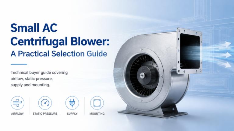
Learn how to select a compact AC blower using its working airflow, pressure, electrical supply and installation needs, with a Yian Electric product example.