Cooling Fan for Solar Inverter: How to Select the Right One
Published: Author: Rachel
Selecting a cooling fan for solar inverter cabinets starts with the heat load the enclosure has to reject, not with the fan diameter. A PV inverter fan works outdoors, inside a cabinet that can sit well above 60 °C in summer, and it is expected to run for years without anyone touching it. That combination makes bearing type, ingress protection and speed control more important than a big airflow number on a catalogue page. This guide covers the inputs you need, the airflow calculation, and the parameters that decide whether the fan survives its first hot season.
A note on terminology before we start: this article is about fans that cool photovoltaic inverters — the equipment that converts DC from a solar array into AC for the grid. If you are looking for fans that cool the electric motors driven by a variable frequency drive, that is a different application covered in our inverter motor cooling fan selection guide.
Why Solar Inverter Cooling Is a Different Problem
An inverter is not a general-purpose electrical cabinet with a few warm components inside. It converts the full output of an array, and the power semiconductors, magnetic components and DC-link capacitors involved in that conversion generate heat continuously for as long as the sun is up. The inverter must then reject that heat into an outdoor environment it does not control.
How Inverter Cooling Differs from Ordinary Panel Cooling
Four constraints separate inverter cooling from ordinary panel cooling:
Continuous duty at high load. Rooftop and utility-scale inverters run at high output for six to ten hours a day, and often at reduced load around the clock. Unlike an intermittent industrial process, there is no natural cooling-off period.
Outdoor exposure. Sun, rain, dust, sand, salt spray, humidity and rodents all act on the fan. A fan that is perfectly adequate inside a clean factory fails quickly outdoors.
High internal temperatures. Cabinet air temperatures in the range of 60 °C to 80 °C are common in hot climates, which pushes fan bearings and lubricants close to their limits.
Low tolerance for downtime. A fan is a moving part, and it will generally fail long before the power electronics do. In a remote or rooftop installation, a fan failure is not a nuisance — it is a site visit.
The Real Cost of Inadequate Cooling
The consequence of poor cooling is not a clean failure. Most string inverters begin to derate — deliberately reduce output — once internal temperatures pass a threshold, and the derating point is typically somewhere in the region of 45 °C to 50 °C ambient for air-cooled string units. The exact figure and the derating slope are model-specific and should always be read from the inverter datasheet rather than assumed from a general rule. What matters for fan selection is the direction of the effect: an undersized or failing fan does not stop the plant, it quietly reduces yield for weeks before anyone notices.
Elevated temperature also shortens component life. A widely used rule of thumb in power electronics is that every 10 °C of sustained over-temperature roughly halves the life of electrolytic capacitors. Treat it as an approximation, not a formula — but it explains why cooling reliability is treated as an asset-life issue rather than a spare-parts issue. It is also the reason any cooling fan for solar inverter cabinets is specified on reliability rather than on purchase price.
Passive or Forced Cooling: Does Your Inverter Actually Need a Fan?
Not every inverter needs a fan, and adding one is not automatically an improvement. There are two cooling strategies, and the choice is made at the system design stage:
The Two Cooling Strategies Compared
Approach
How it works
Where it fits
Passive (natural convection)
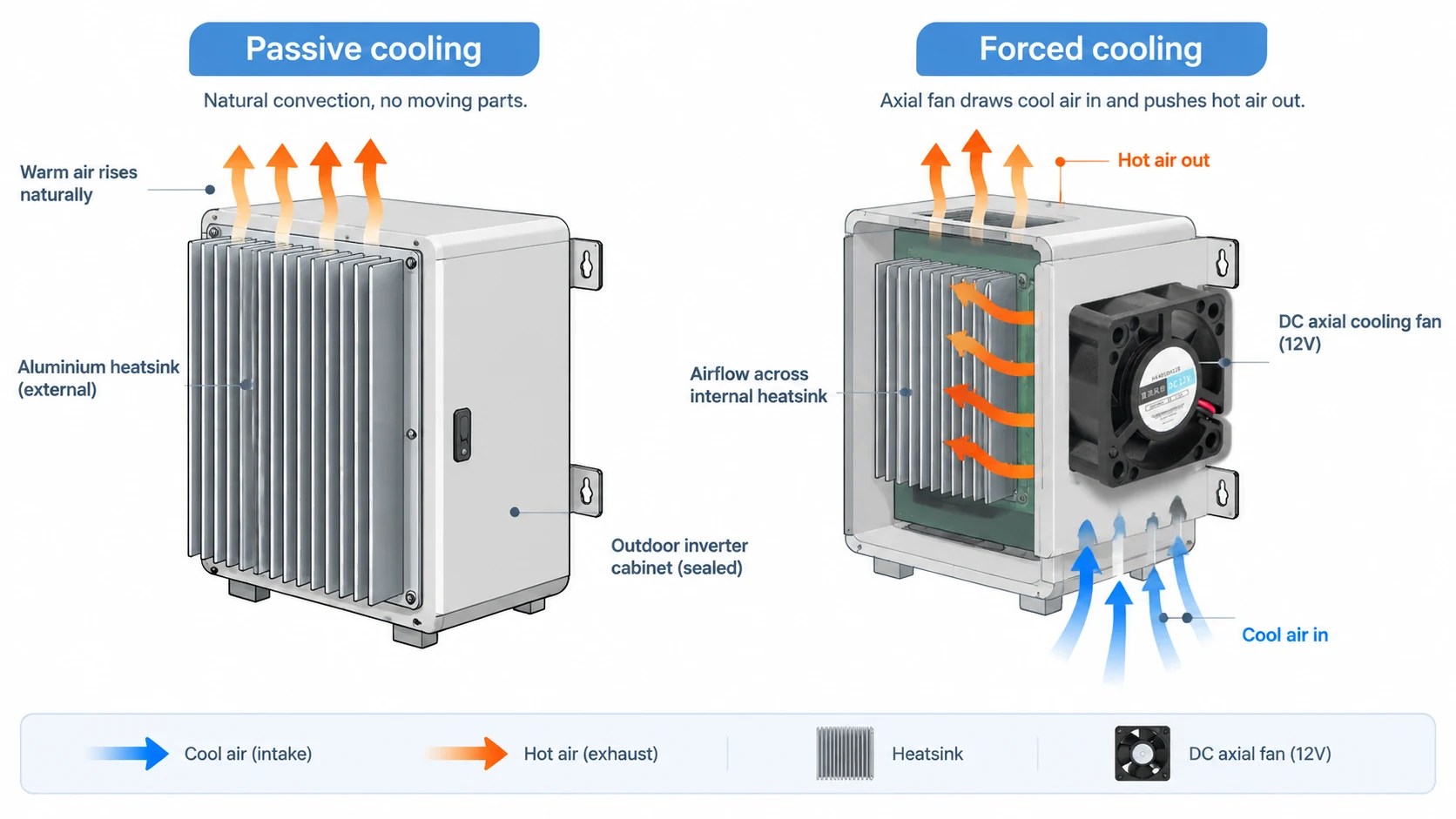
Heat conducts into an external heatsink and dissipates through fins by natural air movement
Low power density units, sealed enclosures, dusty or corrosive sites where moving air is a liability
Active (forced air)
One or more fans move air across the heatsink or through the cabinet
Higher power density, high ambient temperatures, compact enclosures with limited heatsink area
Passive heatsink cooling versus forced-air cooling with a DC axial fan in a solar inverter enclosure.
When Forced Cooling Becomes Necessary
Forced cooling becomes necessary when the passive path can no longer hold the internal temperature within the design limit. That happens when power density rises inside a fixed enclosure volume, when ambient temperature is high, when the enclosure is sealed tightly enough to block natural convection, or when several units are installed side by side with limited spacing between them.
The Ingress Protection Trade-Off
One trade-off deserves attention early. A fan requires openings, and openings compromise the enclosure’s ingress protection. If the enclosure must stay at IP65 or better, direct ventilation is usually not an option — the design moves to an internal air circuit with a heat exchanger, or to an IP-rated fan with a labyrinth air path. This is a cabinet-level decision with its own logic, which we cover separately in the electrical cabinet cooling fan selection guide. For the rest of this article we assume the cabinet is designed for ventilated cooling and the question is which fan to put in it.
How to Size a Cooling Fan for a Solar Inverter
Fan selection should begin with a number, not with a product. The number is the airflow required to carry the heat load away at an acceptable temperature rise.
The Heat Balance Formula
The starting point is the basic heat balance for air passing through an enclosure:
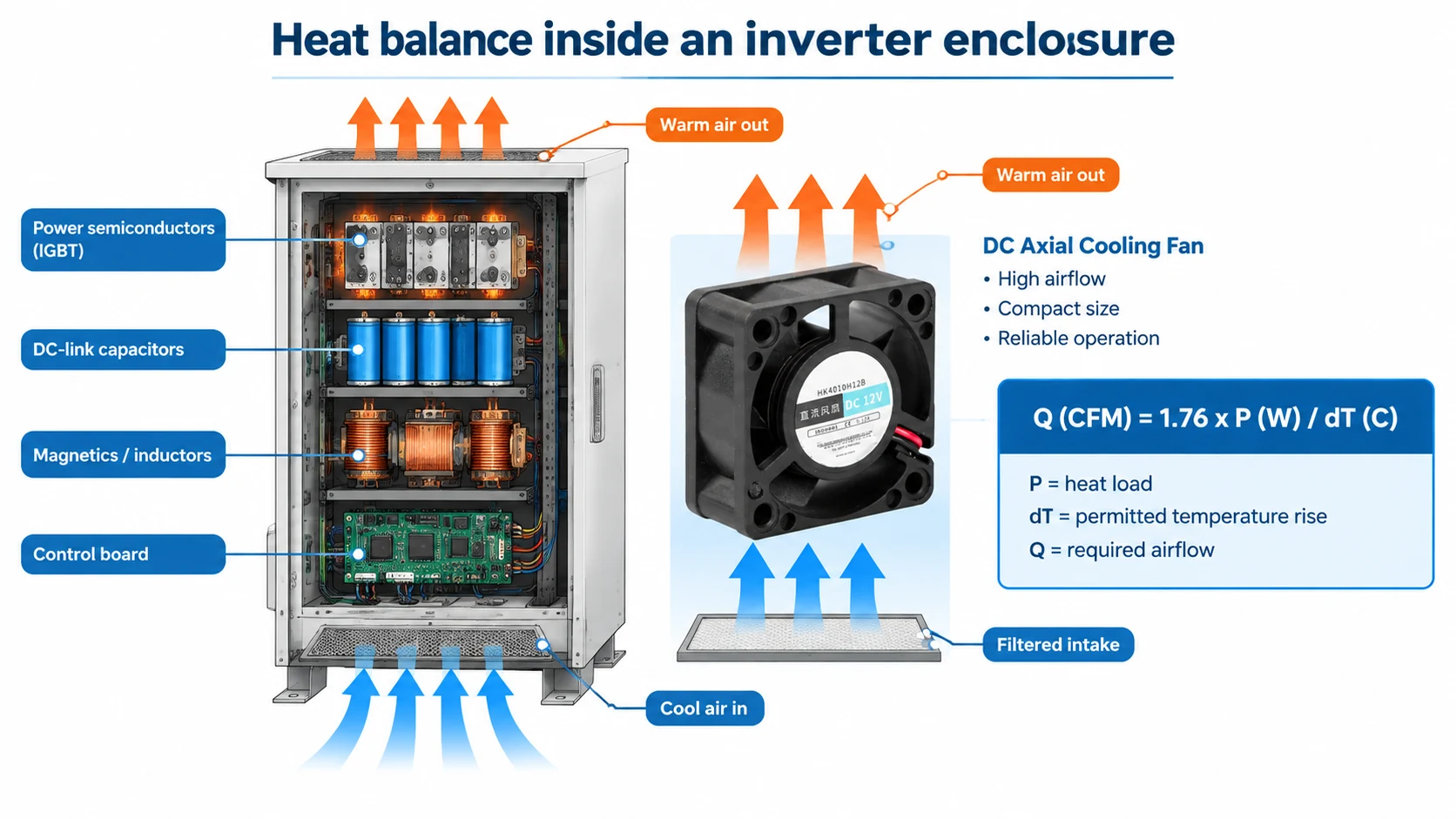
Q = P / (ρ × cp × ΔT)
where Q is volumetric airflow in m³/s, P is the heat load to be removed in watts, ρ is air density (about 1.2 kg/m³ at 20 °C at sea level), cp is the specific heat of air (about 1005 J/(kg·K)), and ΔT is the permitted temperature rise of the air in Kelvin.
The Practical CFM Formula
For practical work it is easier to use the rearranged form with airflow in CFM and temperature rise in °C, which gives:
Q (CFM) ≈ 1.76 × P (W) / ΔT (°C)
This is a first-order estimate. It assumes sea-level air density, ignores the resistance of the air path, and gives the airflow the fan must actually deliver at its working point — not the free-air figure printed on the datasheet.
A Worked Example
Take a string inverter cabinet where the total heat load inside the enclosure — semiconductor losses, magnetics and control electronics combined — is 300 W, and the design allows the internal air to run 10 °C above outside ambient:
Q ≈ 1.76 × 300 / 10 ≈ 53 CFM
So roughly 53 CFM of air has to move through the enclosure. Three corrections usually push the final selection well above that figure.
Three Corrections to the Base Figure
System resistance. Filters, grilles, fins and bends all reduce delivered airflow. A fan rated at 53 CFM in free air may deliver far less once it is pulling through a dust filter and pushing across a finned heatsink. Select the fan from its pressure–flow curve at the system’s operating point, not from the headline airflow value.
Altitude. Air density falls with elevation, and so does the mass flow a fan can move. Above roughly 1000 m, derating the airflow figure is standard practice; at 2000 m the loss is in the order of 15 % to 20 %.
Fouling margin. Outdoor fan performance degrades as dust accumulates on blades, guards and filters. A margin of 1.5× to 2× over the calculated figure is a common starting point for sites where cleaning happens once or twice a year.
Heat balance inside an inverter enclosure: heat load P, permitted rise ΔT and the resulting airflow requirement Q.
Applying a 1.5× margin to the example gives a working target of about 80 CFM. That can be met by one larger fan, two smaller fans in parallel sharing the flow, or a fan running well below its maximum speed — and which of those is best depends on the airflow path inside the enclosure.
Special Case: Cooling a Heatsink Directly
There is an important special case. When the fan blows directly onto a heatsink rather than ventilating the cabinet volume, the flow is impingement cooling: the fan must overcome the concentrated resistance of the fin stack, and static pressure at the operating point matters far more than free airflow. If your fan mounts on a heatsink, select on static pressure first.
Which Fan Voltage Should You Use?
An inverter already contains a regulated auxiliary supply for its control board, sensors and communications. The cheapest and most reliable fan is the one that runs directly from a rail that already exists.
Fan Voltage Options at a Glance
Voltage
Typical use
Considerations
12 V DC
Control-board rail in small and residential string inverters
Most common choice for compact axial fans; check the rail’s spare current capacity
24 V DC
Industrial string inverters, energy storage cabinets, PCS auxiliary supplies
Lower current for the same power, which reduces cable losses over longer runs
48 V DC
Battery racks and larger storage systems
Often matches the battery bus, avoiding an additional conversion stage
230 V AC
Some central inverters and retrofits where a DC rail is not accessible
Simple to wire, but adds an AC circuit inside a DC-dominated enclosure
Why Adding a DC-DC Converter Is Usually the Wrong Answer
Adding a DC-DC converter purely to feed a fan is usually a bad trade. It costs money, occupies board space, adds a switching stage that can radiate noise into sensitive measurement circuits, and introduces one more component that can fail. Match the fan to an existing rail wherever the design allows.
How Voltage Affects Speed, Airflow and Power
Voltage also affects performance more than people expect. For a given fan, airflow is approximately proportional to speed, static pressure to the square of speed, and power consumption to the cube of speed. Run a 12 V fan on a sagging 10 V rail and it will turn noticeably slower and move meaningfully less air, even though it still runs. Check the fan’s rated voltage tolerance and confirm the rail holds up under full inverter load. For 12 V and 24 V DC options in compact frames, see our DC small axial fans.
Bearing Type and Rated Life: Where Fan Reliability Is Decided
Most fan failures in outdoor equipment are bearing failures. The bearing system therefore deserves more attention than any other specification on the datasheet.
Sleeve, Single Ball and Dual Ball Bearings
Bearing type
Strengths
Weak point in inverter service
Sleeve (plain bearing, oil-impregnated)
Low cost, quiet at low speed
Depends on an oil film that migrates and evaporates faster at high temperature; poor choice for hot, continuously running outdoor equipment
Single ball bearing
Better temperature tolerance than sleeve, moderate cost
Still has one plain-bearing surface; usually paired with a sleeve on the opposite end
Dual ball bearing
Best high-temperature tolerance and the most predictable life; handles shaft loads and mounting in any orientation
Higher cost and slightly more audible than a sleeve bearing at low speed
What L10 Life Actually Tells You
Fan life is normally stated as an L10 life: the number of hours at which 10 % of a population is expected to have failed. Figures in the range of 50,000 to 70,000 hours are commonly quoted for dual-ball-bearing fans at rated temperature, which corresponds to six to eight years of continuous operation. Two cautions apply. First, the quoted figure is tied to a reference temperature — running at a higher ambient shortens it, and the relationship is steep rather than linear. Second, the number describes statistical survival in a controlled test, not a guarantee for your specific enclosure, dust loading and duty cycle.
For anything other than a small residential unit that is easy to reach and service, specify dual ball bearings. The incremental cost is a small fraction of the inverter’s value, and it is the single change most likely to keep the fan alive through its second summer. Long-life quiet DC fans with dual ball bearings are covered in our DC small quiet fan range.
IP Rating, Coatings and Materials for Outdoor Survival
A fan mounted in an outdoor inverter is an exposed component. Ingress protection and material selection decide whether it survives the environment rather than the heat.
Choosing the Right IP Rating
IP54 resists dust ingress and splashing water; IP55 adds protection against water jets; IP68 covers continuous immersion. For outdoor inverter cooling, IP55 is a common baseline and salt-spray-exposed or coastal sites justify IP68 or an equivalent sealed construction. Note that a fan’s IP rating applies to the fan itself and does not transfer to the enclosure it is fitted into.
Conformal Coating and UV-Stable Materials
A conformal coating on the fan’s circuit board resists moisture, condensation and corrosive airborne contaminants. It adds little cost and is one of the most effective upgrades for humid or coastal sites.
Materials matter just as much. Flame-retardant PBT or PP for the housing, and PPS or a similarly UV-stable material for the impeller, are common choices for outdoor equipment. Cheap impellers embrittle under UV and crack.
Salt Spray and Coastal Installations
Coastal and offshore installations should reference the fan’s salt-spray test duration rather than assuming a generic outdoor rating is sufficient.
Remember that ventilation and protection pull in opposite directions. Every opening made for airflow is a path for dust, moisture and insects. Guards, filters and labyrinth paths help, but they also raise system resistance — which is why the airflow calculation above must be done at the working point, not in free air.
Speed Control, Noise and Fault Feedback
Three control features separate an inverter-grade fan from a general-purpose one, and all three matter more in remote installations than in a workshop.
PWM Speed Control
A PWM input lets the inverter run the fan only as fast as the present thermal load requires. That reduces noise, cuts fan power consumption, and — because bearing life depends strongly on speed and temperature — extends service life. In cold weather the fan can sit at a low duty cycle instead of running flat out.
Tachometer (FG) and Locked-Rotor (RD) Outputs
A frequency-generator output reports actual fan speed, and a rotation-detection signal flags a stalled rotor. Without one of these, the inverter cannot distinguish a working fan from a dead one. This is exactly how most “fan abnormal” alarms on PV inverters are generated, and without the signal the failure stays invisible until internal temperature climbs. Both signals are essential for any site monitored remotely.
Soft Start and Electrical Protection
Soft-start circuitry limits inrush current, and over-current and locked-rotor protection prevent a stalled fan from sitting there drawing current and heating up.
Noise and Residential Installations
Noise usually sits behind reliability in the specification, but it becomes a real constraint for residential rooftop systems, where a fan running at full speed at the wrong moment is a complaint. Noise is rated as sound pressure level in dB(A), normally measured at one metre. Slower-running fans are dramatically quieter, so a PWM-controlled fan that spends most of its life at mid-speed is both quieter and longer-lived than a fixed-speed fan sized for worst-case load. When the design calls for minimum acoustic signature, a larger fan turning slowly beats a small fan turning fast for the same airflow, and fan mounting should isolate vibration from the enclosure panel.
Size, Mounting and Airflow Direction
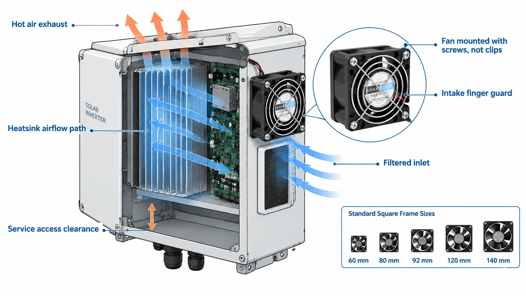
Fan mounting position, intake protection and heatsink airflow path inside an inverter enclosure.
Standard Frame Sizes and Thickness
Inside an inverter, fan selection is constrained as much by space as by performance. Standard square frame sizes run from about 40 mm through 60, 80, 92, 120 and 140 mm, with thicknesses typically between 10 mm and 38 mm. Compact enclosures usually push the design toward thin frames or toward several small fans distributed along the heatsink.
Mounting Rules That Keep the Fan in Place
Fix with screws, not clips. Inverters on rooftops, carports and industrial structures see vibration. A screw-fixed fan with a retaining guard stays where it was installed.
Respect the airflow path. A fan pushing air across a heatsink and a fan exhausting air out of a cabinet are doing different jobs with different resistance characteristics. Decide which one you are doing before choosing the model.
Intake Protection and Service Access
Protect the intake. A finger guard stops debris; in dusty environments a filter is worth considering, accepting that it must be cleaned on a schedule and that it raises resistance.
Leave service access. Fans are the part most likely to be replaced, and a fan that requires partial disassembly of the inverter to reach will be neglected in practice.
Clearance: The Problem That Looks Like a Fan Failure
One frequent misconception: poor cooling that looks like a fan problem is often a clearance problem. Manufacturers typically require several tens of centimetres of free space around ventilated faces, and inverters installed flush against a wall or stacked too closely cannot breathe no matter which fan is fitted. Check the installation clearance before concluding the fan is at fault.
Common Fan Selection Mistakes
Choosing on free-air airflow. The catalogue airflow figure is measured with no resistance. In a real cabinet with a filter and a finned heatsink, a fan selected on that number will under-deliver by a wide margin. Always select at the operating point on the pressure–flow curve.
Saving money on bearings. A sleeve-bearing fan is the single most common cause of repeat failures in hot outdoor equipment. Pay the small premium for dual ball bearings.
Adding a DC-DC stage to feed the fan. Use a rail that already exists in the inverter and eliminate a conversion stage, its losses and its failure point.
Ignoring the voltage tolerance. A fan that runs slowly because the auxiliary rail sags at full load is an under-performing fan, even though it spins.
Fitting a general-purpose fan outdoors. Without adequate IP protection, conformal coating and UV-stable materials, the fan fails from the environment rather than from wear.
Omitting the tachometer or alarm output. Without speed feedback, fan failure is invisible to remote monitoring, and the first symptom becomes reduced yield rather than an alert.
Forgetting fouling margin. Airflow declines as dust accumulates. Sizing exactly to the calculated figure guarantees under-cooling before the first cleaning visit.
Blaming the fan for a clearance problem. Inadequate space around the enclosure is an installation issue that no fan selection can fix.
Cooling Fans from Yian Electric for Inverter Applications
Yian Electric manufactures AC and DC axial fans, external rotor fans and compact centrifugal blowers used in equipment cooling, including power conversion and outdoor enclosure applications. For inverter cooling, the relevant families are the small DC fan range for control-board voltages, dual ball bearing models where continuous high-temperature duty is expected, and low-noise versions for residential installations. Frames are available in compact sizes suitable for dense enclosures, and specifications can be matched to your required voltage, airflow and mounting arrangement.
Because fan performance depends heavily on the airflow path it is installed into, we recommend sending the enclosure layout, heat load and available supply rail alongside your enquiry. That is usually enough to narrow the options quickly, and it avoids the common outcome of a correctly rated but incorrectly matched fan.
Conclusion
Choosing a cooling fan for a solar inverter is a short sequence: calculate the airflow the heat load requires, correct that figure for system resistance, altitude and fouling, then choose the fan on bearing type, IP protection, voltage match and control features rather than on headline airflow. The calculation tells you how much air you need. The remaining parameters decide whether the fan is still there in five years.
If you are working through a specific inverter enclosure and want a shortlist based on your heat load, supply voltage and available space, get in touch with the details and our team will come back to you with suitable options.
Frequently Asked Questions
How do I calculate the airflow needed to cool a solar inverter?
Estimate the total heat load inside the enclosure in watts and the temperature rise you are willing to allow, then use Q (CFM) ≈ 1.76 × P (W) / ΔT (°C). For a 300 W heat load with a 10 °C permitted rise, that gives about 53 CFM. Because filters, heatsink fins and altitude all reduce delivered airflow, apply a margin — 1.5× is a common starting point — and confirm the fan delivers the required flow at the system’s actual operating point on its pressure–flow curve.
Can I use a standard AC fan to cool a solar inverter?
It can work where the enclosure is ventilated and a suitable AC supply is available, but it is usually the wrong choice for a modern inverter. An AC fan cannot be speed-controlled from the inverter’s thermal controller, draws more power, and adds a mains circuit inside a DC-dominated enclosure. A DC fan running from an existing auxiliary rail is normally simpler and better matched.
Why do solar inverter cooling fans fail so often?
Because they are the only moving part in an otherwise static assembly, and they work in the harshest location in the system. Heat degrades bearing lubricant, dust and debris increase load, sunlight degrades plastic components, and rodent or insect damage to wiring is a recurring cause in field installations. Most failures trace back to bearing wear or blockage rather than to electrical failure, which is why bearing type and IP protection deserve early attention.
Does fitting a cooling fan reduce the enclosure’s IP rating?
Direct ventilation always creates an opening, so yes, unless it is designed around. Options include an IP-rated fan with a labyrinth air path, an internal air circuit with a heat exchanger rather than open ventilation, or accepting a lower cabinet IP rating with filtered openings. The fan’s own IP rating describes the fan and does not automatically preserve the enclosure rating.
How long should a solar inverter cooling fan last?
Dual ball bearing fans are commonly quoted at 50,000 to 70,000 hours of L10 life at a reference temperature, which is roughly six to eight years of continuous operation. Real service life is usually shorter, because dust loading, high ambient temperature and speed all accelerate wear. The reference temperature matters: running significantly above it reduces life disproportionately, so a fan running at reduced speed in a cooler part of its range will last considerably longer than one running flat out.
What voltage fan do solar inverters use?
Compact string inverters most often use 12 V DC fans running from the control-board rail, while larger industrial inverters and energy storage cabinets commonly use 24 V or 48 V DC, frequently matching a battery or auxiliary bus. Some central inverters and retrofit installations use 230 V AC fans. The correct choice is the one that runs from an existing supply in your design, since adding a conversion stage costs money, wastes power and introduces another failure point.
Axial fan vs centrifugal fan compared for engineers: pressure, PQ curve, noise, efficiency, space, maintenance and drive type, with a duty decision table and a three-step selection method.
A symptom-first guide to an exhaust fan not working: five failure patterns, power, control and capacitor checks, bearing faults, air-path blockages, and how to match a replacement fan.
Industrial exhaust fan noise has three distinct families - aerodynamic, mechanical and electromagnetic - and each needs a different fix. This guide gives a five-step field diagnosis, then covers source-first remedies: speed reduction, balancing, bearings, vibration isolation, silencers and placement, with the airflow trade-offs made explicit.