Industrial Exhaust Fan Selection for Factory Workshops
Published: Author: Rachel
Industrial exhaust fan selection for a factory workshop starts by defining the ventilation problem, calculating the room volume, choosing a justified air-change target, and converting that target into airflow. The fan must then deliver that airflow against the real resistance of louvers, guards, filters, ducts, bends, and discharge fittings. Fan diameter alone does not establish performance. The same principle applies at every scale, from a workshop exhaust fan down to the cooling fan in a solar inverter cabinet.
For preliminary whole-room ventilation, use airflow (m³/h) = workshop volume (m³) × air changes per hour (ACH). This is a planning calculation. Welding fumes, solvent vapors, combustible dust, and other process contaminants may require local exhaust ventilation designed from capture velocity, hood geometry, exposure limits, and applicable regulations.
What Should a Factory Exhaust System Accomplish?
A workshop exhaust system removes warm or contaminated indoor air and creates a controlled path for replacement air. Its purpose may be heat relief, dilution of general odors, removal of humid air, or support for a process-specific extraction system. State the purpose before selecting equipment because each problem leads to a different airflow and layout.
General ventilation is appropriate when heat or low-hazard contaminants are distributed through a large space and fresh air can mix effectively. Local exhaust is usually more effective when contaminants are released from a specific machine, tank, welding point, or dust-producing process. Capturing material close to the source can require much less air than trying to dilute it after it spreads through the workshop.
Information Needed Before Industrial Exhaust Fan Selection
Input
Why it matters
Workshop length, width, and average clear height
Defines the room volume used for the initial ACH calculation.
Heat and contaminant sources
Determines whether general ventilation, local extraction, or both are required.
Operating schedule and occupancy
Shows when full airflow is needed and whether staged or variable control is useful.
Doors, windows, louvers, and nearby buildings
Controls where makeup air can enter and whether exhaust may recirculate.
Wall, roof, or duct route
Sets available space and system resistance.
Dust, oil mist, moisture, chemicals, and air temperature
Affects fan construction, protection, cleaning, and safe suitability.
Electrical supply and control method
Must match voltage, phase, frequency, starter, protection, and speed-control needs.
Noise limits and nearby occupied areas
Influences fan quantity, speed, location, isolation, and silencing.
Calculate Workshop Volume
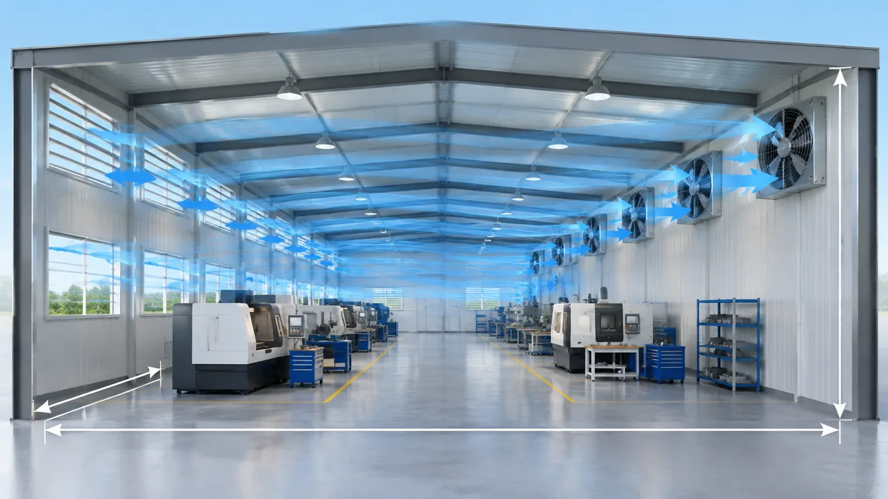
For a rectangular workshop, calculate internal volume as:
Use the average ventilated height where the roof slopes. Subtracting every machine is usually unnecessary for an early estimate, but large enclosed rooms, mezzanines, ovens, storage blocks, or partitions can alter the effective air path. Divide complex buildings into zones when air cannot mix freely between them.
Choose an Appropriate Air Changes per Hour Target
ACH describes how many room volumes of air are supplied or exhausted in one hour. It is a simple way to estimate general ventilation, but there is no universal ACH value for every factory. A justified target depends on process heat, contaminant generation, occupancy, climate, building leakage, and local codes or industrial-hygiene requirements.
Use a value from the applicable design standard, authority requirement, process guidance, or a ventilation engineer. If no verified target is available, treat any assumed ACH as a scenario for budgeting rather than a final design criterion. Compare several scenarios to understand how strongly the fan requirement changes.
Airflow calculation formula
Q = V × N
Q = required general-ventilation airflow, in m³/h
V = ventilated workshop volume, in m³
N = selected air-change rate, in changes per hour (h⁻¹)
Practical calculation example
Assume a workshop is 30 m long, 20 m wide, and 6 m high. Its gross volume is:
V = 30 × 20 × 6 = 3,600 m³
If the project engineer selects 8 ACH for a preliminary general-ventilation scenario, the calculated airflow is:
Q = 3,600 × 8 = 28,800 m³/h
The 28,800 m³/h result is the total nominal room-air requirement before checking static pressure, leakage, wind, filter loading, temperature, altitude, fan tolerances, and the effectiveness of air distribution. It could be divided among several fans to reduce dead zones and provide staged operation. The final quantity must come from fan curves at the installed duty point.
To request an initial recommendation, send Yian Electric the workshop dimensions, selected ACH or required airflow, process description, installation route, environmental conditions, electrical supply, and expected quantity.
Convert Required Airflow into an Installed Duty Point
A catalog airflow value is meaningful only with its test condition and unit. Free-air ratings describe operation with very little external resistance. Real installations add pressure loss through an inlet grille, shutter, insect screen, weather hood, duct, bend, damper, silencer, or filter.
Add the pressure losses of the proposed system and plot the resulting system curve. Select a fan whose performance curve intersects the required airflow near a stable and efficient part of its operating range. Ask whether the published airflow is free air or a rated value at pressure, and do not convert between m³/h and CFM without checking the source unit.
Allow for fouling and operating conditions
Dust buildup, loaded screens, reduced air density at altitude, hot inlet air, and manufacturing tolerances can reduce delivered airflow. Apply allowances based on known site conditions and the relevant engineering standard. One fixed safety percentage is not suitable for every workshop; a dusty foundry and a clean assembly room do not derate in the same way.
Wall-Mounted vs Ducted Exhaust Fan Installation
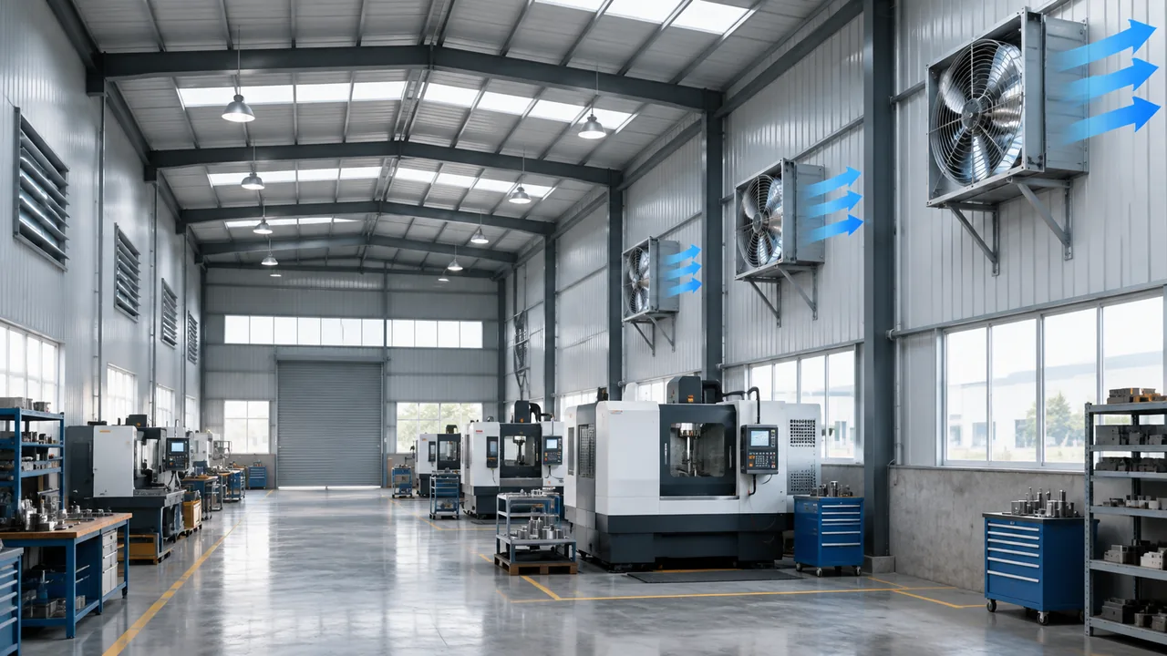
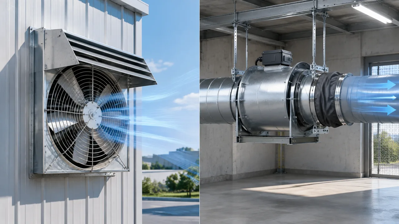
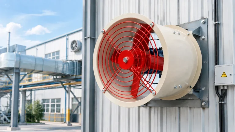
Wall-mounted fans are effective when air can discharge directly outdoors through a short opening. The low-resistance path suits axial fans and keeps installation simple. Include the pressure loss of guards, shutters, louvers, and weather protection. Place the discharge where exhausted air cannot be drawn back into doors, windows, or intake openings.
Ducted fans serve interior zones or carry air to a safe discharge point. Ducts add resistance, especially when they are narrow, long, flexible, dirty, or fitted with multiple bends. A housed axial fan may work for a short, low-resistance route, while a higher-pressure axial or centrifugal design may be required as resistance increases.
For a ducted arrangement, support the duct independently so its weight does not distort the fan housing. Provide access for cleaning and inspection. Check transitions, backdraft dampers, flexible connectors, vibration isolation, and discharge protection as part of the complete system.
How to Choose Fan Size and Quantity
Choose fan size from the required airflow and pressure rather than opening diameter alone. A larger, slower fan may reduce aerodynamic noise for the same low-pressure airflow, but available wall space, guard dimensions, wind loading, and structural support still matter. Several smaller fans can distribute airflow across a wide workshop and allow staged control, while one large fan can simplify wiring and maintenance.
When using multiple fans, divide the total airflow only after accounting for each fan’s installed operating point. Fans mounted close together can interact with common shutters or restricted intake areas. Space them so each unit receives uniform air and so maintenance access remains available.
Plan Fan Location and Airflow Direction
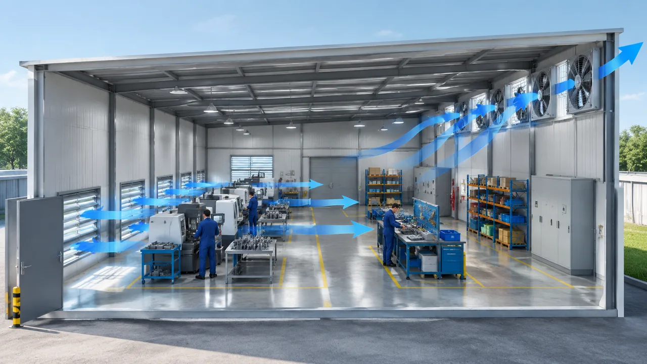
Place exhaust openings near the heat or contaminant path and place makeup-air openings on the cleaner side of the workshop. For buoyant heat, high-level exhaust can remove the rising warm layer. For a specific contaminant, location must follow its source behavior and the local-exhaust design rather than a simple high-wall rule.
Create a crossflow that sweeps occupied and process zones without short-circuiting directly from an intake to a nearby exhaust fan. Use smoke visualization, anemometer readings, temperature mapping, or contaminant measurements during commissioning to find stagnant pockets.
Balance Intake and Exhaust Air
Every cubic metre exhausted must be replaced. If makeup-air openings are too small, the fans pull the building into excessive negative pressure. Delivered airflow falls, doors become difficult to open, combustion appliances may backdraft, and air enters through uncontrolled gaps carrying dust or outdoor heat.
Size intentional intake paths for acceptable velocity and pressure loss. Depending on the process, the building may be kept slightly negative to contain contaminants, neutral for general comfort, or positive to exclude outdoor dust. The pressure relationship should be designed, measured, and coordinated with process exhaust, heating, cooling, and combustion air.
Noise, Vibration, and Speed Control
Fan sound depends on speed, blade design, operating point, guards, turbulence, structure, and the room’s acoustic surfaces. Compare sound data for the exact model and test condition. A fan mounted in a lightweight wall panel can transmit vibration even when its catalog sound level appears acceptable.
Reduce noise by avoiding undersized high-speed fans, selecting a stable operating point, using rigid supports and suitable isolators, keeping inlet flow unobstructed, and locating fans away from quiet work areas. Variable or staged control can reduce airflow and sound during low-load periods, provided minimum ventilation and process-safety requirements remain satisfied.
Dust, High Temperature, Corrosion, and Hazardous Air
Standard general-ventilation fans should not be assumed suitable for abrasive dust, sticky mist, corrosive vapor, hot air, or an explosive atmosphere. Deposits can unbalance blades and block guards. High air temperature can exceed motor, bearing, insulation, or plastic-component limits. Corrosive material can attack blades, housings, fasteners, and protective coatings. Equipment-level cooling is a separate problem, covered in our guide to the cooling fan for welding machine.
Provide the normal and maximum air temperature, dust type and concentration, moisture, oil mist, chemicals, cleaning method, and any hazardous-area classification. Combustible dust and flammable vapor require a documented hazard assessment and appropriately certified equipment. Yian Electric lists a separate explosion-proof exhaust fan; suitability still depends on the exact zone, gas or dust group, temperature class, and local approval requirements.
Relevant Yian Electric Fan Options
The provided AC external rotor axial fan is intended for local ventilation and lists suction and blowing versions. Its published YWF range includes 220 V and 380 V configurations, multiple diameters, stated IP54 or IP55 protection, and model-specific airflow and noise values. Use the current fan curve and drawing to confirm the workshop operating point and mounting.
For a housed installation or short duct connection, review the drum-type AC external rotor axial fan. The page lists wall and ventilation-pipe applications with a cylindrical double-flange housing. Where demand-based speed control is part of the design, the EC external rotor exhaust fan range lists model-dependent control inputs and feedback features.
These pages provide a product shortlist, not a complete ventilation design. Send the calculated airflow, total static pressure, voltage, frequency, mounting arrangement, temperature, contaminants, noise target, and quantity so the proposed model can be checked against current performance data.
Factory Workshop Exhaust Fan Selection Checklist
Define whether the goal is heat removal, general dilution, or source capture.
Measure the ventilated length, width, and average height.
Select an ACH target from an applicable standard or qualified design basis.
Calculate total airflow and keep units consistent.
Map clean makeup-air routes and exhaust locations.
Estimate pressure loss through every grille, shutter, filter, duct, bend, and discharge fitting.
Choose wall-mounted or ducted construction from the actual air path.
Select the number of fans from curves at the installed duty point.
Check voltage, phase, frequency, controls, protection, and isolation.
Verify temperature, dust, moisture, corrosion, and hazardous-area requirements.
Review noise, vibration, structural support, guards, access, and maintenance.
Commission the system by measuring airflow, pressure balance, and problem zones.
Choosing a fan before defining the ventilation problem. Whole-room dilution cannot replace a required capture hood.
Using floor area without ceiling height. ACH calculations require room volume.
Treating an assumed ACH as a regulation. Use the correct project and process criteria.
Ignoring static pressure. A fan’s free-air value may not be delivered behind a louver or duct.
Providing no makeup air. Excessive negative pressure reduces flow and disrupts the building.
Placing intake and exhaust too close. Short-circuiting leaves the workshop poorly ventilated.
Ignoring the air stream. Dust, heat, corrosion, or flammable material may require a different fan.
Skipping commissioning. Measure the finished system instead of assuming catalog performance reached every zone.
Conclusion
Sound industrial exhaust fan selection connects a clear ventilation objective to workshop volume, a justified ACH target, installed airflow and pressure, effective fan placement, and sufficient makeup air. Wall-mounted axial fans work well for short, low-resistance paths; ducted systems require a closer pressure assessment.
For a selection and quotation, send Yian Electric the workshop dimensions, required ACH or airflow, calculated static pressure, wall or duct layout, supply voltage and frequency, temperature, dust or vapor details, noise target, control method, and purchase quantity. This information supports a model recommendation without guessing from fan diameter.
Frequently Asked Questions
How do I calculate exhaust fan airflow for a workshop?
Multiply the ventilated room volume in cubic metres by the selected air changes per hour. The result is m³/h. Treat it as a preliminary whole-room ventilation value and then check pressure losses, air distribution, makeup air, and any process-specific extraction requirement.
How many air changes per hour does a factory need?
There is no single value for every factory. The correct ACH depends on the process, heat and contaminant generation, occupancy, climate, and local requirements. Use a verified standard or qualified ventilation design basis for the specific workshop.
Is a wall-mounted fan better than a ducted fan?
A wall-mounted fan is usually simpler for direct, low-resistance exhaust. A ducted fan can reach an interior source or remote discharge point, but the duct adds static pressure. The better option is the one that creates the required air path and reaches the duty point on the fan curve.
Should intake airflow equal exhaust airflow?
Makeup air must replace the exhausted volume, but the exact supply-to-exhaust balance depends on the desired building pressure. Some workshops need slight negative pressure for containment, while clean spaces may need positive pressure. Measure and control the intended relationship.
Can a standard axial fan exhaust welding fumes or combustible dust?
Do not assume it can. Welding fumes generally need source capture designed for the process. Combustible dust or flammable vapor requires a hazard assessment, suitable collection design, and correctly certified equipment under the applicable rules.
Why is actual airflow lower than the catalog value?
The installed system adds resistance through guards, shutters, louvers, ducts, bends, filters, and discharge fittings. Fouling, altitude, air temperature, and poor makeup-air paths can reduce performance further. Select from the fan curve at the calculated static pressure and verify airflow after installation.
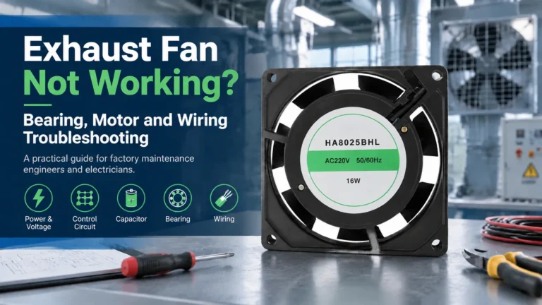
A symptom-first guide to an exhaust fan not working: five failure patterns, power, control and capacitor checks, bearing faults, air-path blockages, and how to match a replacement fan.
Industrial exhaust fan noise has three distinct families - aerodynamic, mechanical and electromagnetic - and each needs a different fix. This guide gives a five-step field diagnosis, then covers source-first remedies: speed reduction, balancing, bearings, vibration isolation, silencers and placement, with the airflow trade-offs made explicit.
A practical guide to selecting and replacing a cooling fan for welding machine enclosures: heat sources, airflow path, fan specs, five common failures, and a step-by-step workshop swap.