An inverter motor cooling fan should be selected from the motor maker’s cooling requirement, the motor frame and mounting interface, the resistance of the airflow path, an independent power supply, and the installation environment. Motor power alone is not enough. A variable-frequency drive can slow the shaft-mounted fan at the same time that the motor still carries substantial load, so cooling must be checked at the lowest operating speed and the most demanding duty point.
This inverter motor cooling fan selection guide gives engineers, OEMs, system integrators, and buyers a practical process for creating a reliable shortlist. Final approval should still use the motor manufacturer’s load-capacity data, the fan curve, the installation drawing, and the applicable electrical and machine-safety requirements.
What Is an Inverter Motor Cooling Fan?
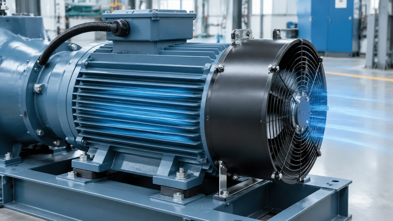
An inverter motor cooling fan is a separately driven fan assembly that moves cooling air over a motor independently of the motor shaft speed. It is also described as a forced-ventilation fan or separately powered cooling fan. The fans that cool photovoltaic inverters in solar plants are a different application, covered in our guide to cooling fans for solar inverter cabinets. In motor documentation, forced ventilation may be identified as an IC416 arrangement, although the exact designation and construction must be confirmed for the motor.
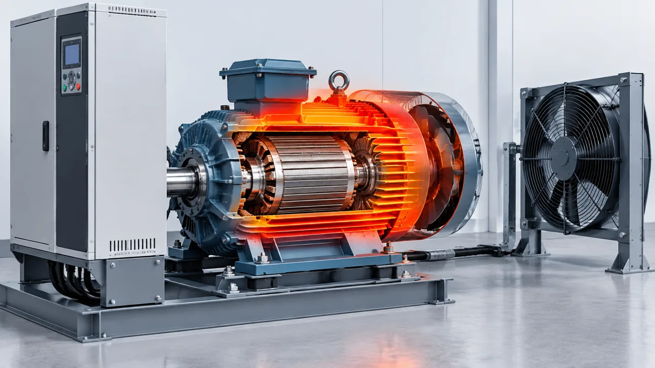
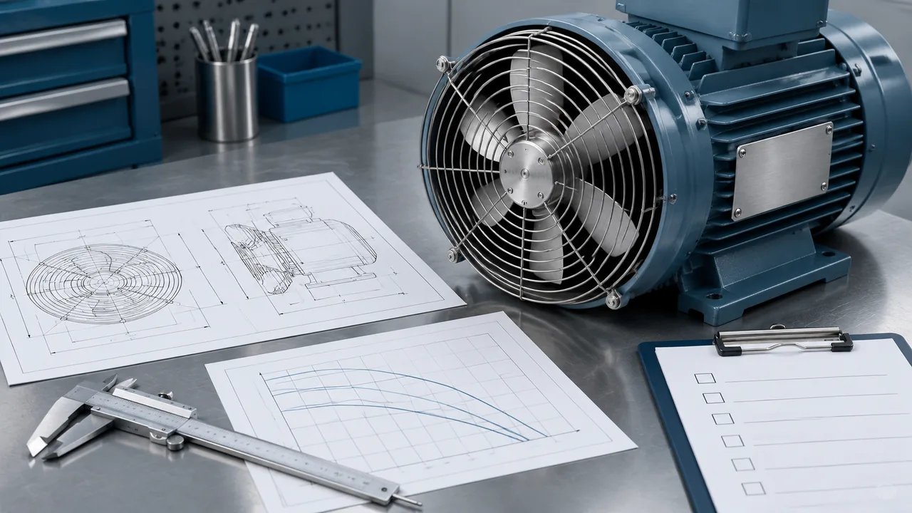
The assembly commonly includes a protective cover, fan motor, and impeller. It mounts at the non-drive end and directs air along the external cooling fins. This differs from a conventional self-cooled motor, whose fan turns with the motor shaft. A separate fan can maintain ventilation when the main motor runs slowly, holds torque at low speed, or pauses while heat remains in the frame.
Why VFD Operation Changes Motor Cooling
A shaft-mounted fan produces less airflow as motor speed falls. The thermal problem is therefore not simply the motor’s rated kilowatts. It depends on losses, torque, speed, duty cycle, ambient temperature, enclosure conditions, and how readily heat can leave the motor surface.
Official motor-and-drive guidance warns that reduced self-cooling at low speed can raise motor surface temperature and reduce allowable load. A separately powered fan can improve low-speed cooling, but it does not automatically make every torque-speed point acceptable. Use the motor maker’s VFD load-capacity curve or written approval, and retain winding or bearing temperature protection where the application requires it.
When Is Separate Forced Cooling Needed?
Consider an external cooling fan when the motor spends meaningful time below the speed at which its shaft fan can provide adequate ventilation. Typical triggers include low-speed constant-torque operation, frequent starts and stops, long dwell periods under load, limited natural air circulation, or a motor maker that specifies forced ventilation for the intended speed range.
Do not add a fan solely because a VFD is present. Some motors are designed and rated for the required variable-speed duty without an auxiliary fan. Others need derating, a larger motor, or a different cooling arrangement. The selection decision should answer three questions:
What torque, speed, and duration define the worst thermal operating point?
What cooling method does the motor manufacturer permit at that point?
Can the proposed fan deliver the required airflow after mounting losses and site derating?
Information to Collect Before Inverter Motor Cooling Fan Selection
A useful request for quotation starts with the motor and duty, not a guessed fan diameter. Collect the following information before comparing products.
Input
Why it matters
Motor manufacturer, type, frame, and serial data
Identifies the cooling requirement and compatible mechanical interface.
Mounting drawing and rear-end dimensions
Confirms flange, bolt pattern, shaft clearance, guard depth, and air outlet geometry.
Minimum and maximum speed
Shows where self-cooling becomes weakest and whether overspeed-related airflow is irrelevant because the auxiliary fan is independent.
Torque/load profile and duty cycle
Defines how much heat is generated and for how long, especially during low-speed constant-torque service.
Ambient temperature, altitude, and location
Affects air density, temperature difference, motor rating, and fan performance.
Dust, moisture, oil mist, chemicals, and washdown
Determines the required enclosure protection, materials, filtration, and maintenance plan.
Fan supply voltage and frequency
Must match the fan nameplate and control circuit independently of the VFD output.
Required airflow or motor maker’s approved fan
Provides the performance target and avoids sizing by diameter alone.
Control and feedback requirements
Defines contactor, overload protection, airflow proof, alarms, and interlocks.
A Practical Selection Process
1. Confirm the motor’s thermal requirement
Start with the motor data sheet, VFD duty chart, and application load profile. Identify the minimum continuous speed, peak torque, duration at each duty point, ambient temperature, and allowable starts per hour. Ask the motor supplier whether forced ventilation is required and what airflow, pressure, or approved fan assembly is specified.
Do not estimate the required fan solely from motor input power or rated output. The heat that reaches the frame depends on motor efficiency, load, harmonic losses, construction, and internal heat paths. A general ventilation equation cannot replace motor-specific thermal data.
2. Match the frame and mechanical interface
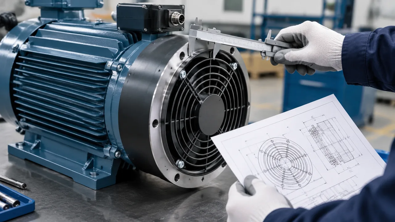
The fan must fit the exact rear-end geometry. Check the motor frame designation, flange diameter, bolt circle, hole count, guard length, shaft or encoder clearance, and the available service space. Similar frame labels from different motor series do not guarantee identical mounting.
Request the fan outline drawing and compare every critical dimension with the motor drawing. Confirm whether the listing is a complete assembly, a Type A or Type B housing arrangement, or a fan supplied without a housing. The product title alone cannot resolve these differences.
3. Check airflow and static pressure together
Free-air volume is only one part of fan performance. Guards, narrow passages, motor fins, screens, and nearby walls add resistance. The installed operating point is where the fan curve meets the system-resistance curve. A fan with a high free-air rating can still underperform if its available pressure is insufficient.
Ask for the applicable fan curve and evaluate it at the resistance of the finished installation. Include the protective cover and any inlet screen in the assessment. Apply a justified allowance for manufacturing tolerance, contamination, altitude, and expected blockage; avoid using one arbitrary percentage for every application.
4. Verify airflow direction and clearance
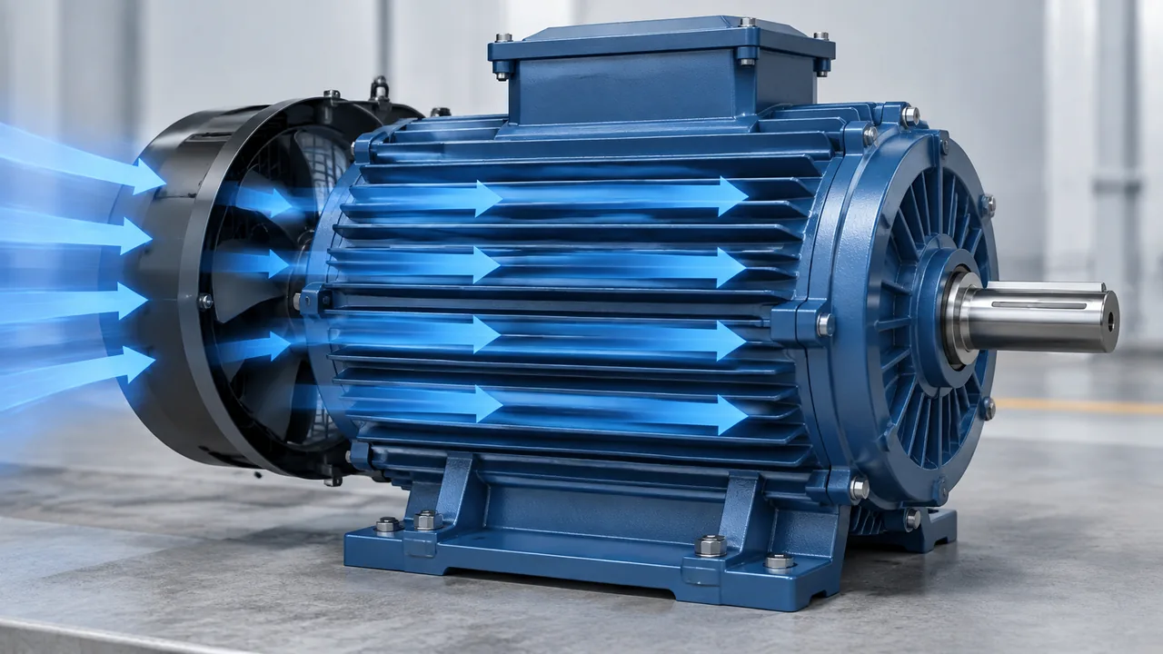
For the common rear-mounted arrangement, the fan drives cooling air along the motor’s external fins toward the drive end. Confirm the required direction from the motor drawing and the fan’s rotation or airflow arrow. Reversed airflow, a loose shroud, or a large gap between the guard and motor body can reduce cooling where it is needed.
Keep the inlet clear of panels, cable trays, walls, and accumulated debris. Provide enough clearance for uniform air entry and future removal. Where hot process air could be recirculated into the inlet, change the equipment layout or duct the air according to an engineered design.
5. Select voltage, frequency, and control method
The auxiliary fan normally uses a separate supply so its speed does not fall with the VFD-driven motor. Match the actual fan nameplate for voltage, phase, frequency, current, and connection. Never assume that a fan can be connected to the VFD output or that a 50 Hz rating is interchangeable with 60 Hz.
A typical control sequence starts the cooling fan before enabling loaded low-speed operation and keeps it running long enough to remove residual heat after the main motor stops. The correct sequence depends on the machine risk assessment and motor maker’s instructions. Consider a fan contactor, branch protection, overload protection, a run-feedback contact or airflow switch, and a trip or derating response if cooling is lost.
6. Check the environment and protection level
IP ratings describe enclosure protection under specified tests; they do not prove suitability for every contaminant. Dust can coat blades and block fins. Oil mist can attack insulation or form deposits. Moisture can enter through an unsuitable orientation or cable entry. Corrosive vapors may require different materials or coatings. High ambient temperature affects both fan and motor life.
Compare the fan’s documented temperature, humidity, altitude, duty, and IP limits with the actual site. If the environment exceeds a catalog limit, request a written selection rather than applying the unit unchanged. Also plan safe inspection intervals for the inlet, impeller, fasteners, wiring, and motor cooling fins.
How to Read the Yian Electric G-Series Listing
Yian Electric’s inverter motor cooling fan product page lists G-series assemblies from G-71A through G-355A. The published table shows 380 VAC, 50 Hz models, while the page states that 220 V can be customized. It also states S1 duty, a -15 to +40 °C ambient range, operation up to 1000 m altitude, relative humidity up to 90% at 25 °C, and IP54 or IP55 depending on the model.
The following rows illustrate how published values vary across the range. They are examples for an initial shortlist, not a substitute for the current drawing, fan curve, nameplate, or compatibility confirmation.
Published type
Supply
Power
Speed
Air volume
Pressure
Published IP
G-90A
380 VAC, 50 Hz
30 W
2800 r/min
500 m³/h
80 Pa
IP54
G-160A
380 VAC, 50 Hz
60 W
1400 r/min
1300 m³/h
50 Pa
IP54/IP55
G-315A
380 VAC, 50 Hz
550 W
1400 r/min
5000 m³/h
110 Pa
IP54
Use the type designation as a starting point, then send the motor frame, rear mounting dimensions, required airflow or motor maker’s recommendation, supply, and site conditions for confirmation. Ask Yian Electric for a fan selection and quotation with the expected order quantity and any required housing arrangement.
Common Selection Mistakes
Selecting by motor kilowatts alone. Motors with the same output can have different frames, losses, cooling paths, and duty limits.
Matching only the nominal frame number. Verify the complete mounting drawing, especially when an encoder, brake, or special rear cover is fitted.
Using free-air volume as installed airflow. Evaluate static pressure and system resistance.
Feeding the auxiliary fan from the VFD output without approval. The fan requires the supply and control method shown on its own documentation.
Ignoring fan-failure behavior. Decide whether the machine alarms, derates, or trips when cooling is lost.
Reversing airflow or blocking the inlet. Confirm arrows, phase sequence where applicable, and installation clearance.
Assuming a higher IP number solves every environment. Check dust, moisture, oil mist, chemicals, temperature, and maintenance separately.
Installing a larger fan without checking the system. Extra airflow may add noise and power use, while poor shrouding can still leave hot areas.
Inverter Motor Cooling Fan Selection Checklist
Record the motor maker, full type, frame, rated data, and rear-end drawing.
Define minimum speed, maximum speed, torque profile, duty cycle, starts, and dwell periods.
Obtain the motor maker’s VFD derating or load-capacity guidance.
Confirm whether forced cooling is required and obtain its airflow or approved assembly requirement.
Match flange, bolt pattern, depth, guard, shaft, encoder, and brake clearances.
Check the fan curve against guards, fins, screens, ducts, and installation resistance.
Verify supply voltage, phase, frequency, current, and independent control circuit.
Define start, stop, run-on, alarm, and fan-failure interlock logic.
Reliable inverter motor cooling fan selection begins with the motor’s thermal requirement and VFD duty, then narrows the choice by mechanical fit, airflow at pressure, independent electrical supply, control logic, and environmental limits. A frame label or airflow number by itself cannot confirm compatibility.
For a product recommendation and quotation, send Yian Electric the motor manufacturer and frame, mounting drawing, minimum speed and load profile, required airflow if specified, fan voltage and frequency, ambient conditions, housing arrangement, and purchase quantity. This information allows the supplier to check the proposed fan against the actual installation.
Frequently Asked Questions
Does every VFD-driven motor need a separate cooling fan?
No. The answer depends on the motor design, speed range, load, duty cycle, ambient conditions, and the motor maker’s variable-speed rating. Use the published load-capacity curve or written guidance rather than assuming that every VFD application needs forced cooling.
Can the cooling fan run from the VFD output?
Do not assume it can. A forced-cooling fan is generally separately powered so its airflow remains available at low main-motor speed. Connect it only according to the fan and motor documentation, using the correct supply, protection, and control circuit.
How do I match a cooling fan to the motor frame?
Use the complete motor type and rear-end drawing. Compare flange diameter, bolt pattern, guard length, shaft clearance, and any encoder or brake. The nominal frame is a useful starting point but is not sufficient evidence of fit.
Is a larger cooling fan always safer?
No. The fan must deliver the required airflow at the installed resistance and distribute it over the motor correctly. An oversized unit can add noise, electrical load, and mechanical problems without correcting a poor shroud or blocked air path.
What should happen if the cooling fan fails?
The machine design should define a safe response. Depending on the risk and process, this may include an alarm, load derating, or a controlled trip based on fan feedback or motor temperature. Follow the motor maker’s protection guidance and the machine risk assessment.
What information should I send for a quotation?
Send the motor make, full type and frame, mounting drawing, operating speed and load range, required airflow or approved fan reference, supply voltage and frequency, ambient and contaminants, mounting arrangement, and quantity.
A symptom-first guide to an exhaust fan not working: five failure patterns, power, control and capacitor checks, bearing faults, air-path blockages, and how to match a replacement fan.
Industrial exhaust fan noise has three distinct families - aerodynamic, mechanical and electromagnetic - and each needs a different fix. This guide gives a five-step field diagnosis, then covers source-first remedies: speed reduction, balancing, bearings, vibration isolation, silencers and placement, with the airflow trade-offs made explicit.
A practical guide to selecting and replacing a cooling fan for welding machine enclosures: heat sources, airflow path, fan specs, five common failures, and a step-by-step workshop swap.