How to Select an Axial Fan for Industrial Applications
Published: Author: Rachel
To select an axial fan for an industrial application, define the airflow your process needs, determine the resistance of the complete air path, and choose a model whose performance curve meets both requirements. Then confirm the electrical supply, operating environment, installation drawing and controls before testing the fan in the finished equipment.
Industrial axial fan selection starts with a duty point, not a diameter or a maximum airflow number. A fan that looks suitable on a product page may deliver too little air once a filter, coil, guard or duct is installed. This guide turns the selection process into a specification you can send to a supplier and an acceptance plan you can use on site.
1. Define the Application and Its Operating Envelope
First identify what the air must accomplish. General ventilation replaces air in a space. Equipment cooling removes heat from components or a heat exchanger. Process extraction has additional requirements related to capture and the material being conveyed. These applications should not share an airflow target simply because their fans have similar dimensions.
For industrial equipment, write down the most demanding credible operating condition as well as normal operation. A cooling unit may face its highest heat load on a hot day, while a filtered enclosure may face its highest resistance shortly before filter replacement. These conditions may occur together and should be reviewed as a combined case.
Design input
What to document
Cooling or ventilation task
Heat rejection, fresh-air supply, exhaust or local equipment cooling
Required performance
Airflow and pressure together, with units and test conditions
Operating envelope
Minimum and maximum load, inlet temperature, altitude and filter condition
Power and control
Voltage, frequency, phase, available control signals and fault response
Mechanical interface
Available space, mounting arrangement, air direction and service access
Acceptance criteria
Temperature, airflow, noise, vibration and alarm requirements
Axial designs are often candidates for ventilation and equipment cooling with a relatively open flow path. A restrictive system may need a different axial design or a centrifugal alternative. The Oriental Motor fan-structure guide explains why different fan geometries suit different airflow and pressure requirements. Let the actual curves settle the choice.
If the project is specifically a compact electronics enclosure, the small axial fan selection guide provides the size-focused companion. Here, the emphasis is the industrial system and its documented operating envelope. Where the enclosure is an IT or server rack, the cooling fan for server rack selection guide covers rack heat load to CFM and cabinet-level airflow.
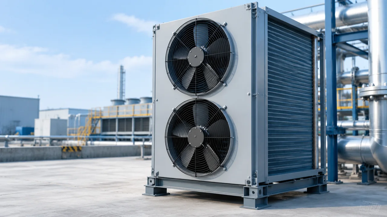
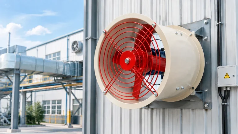
Generated application illustration of industrial heat rejection; not a specific product model.
2. Establish the Airflow Requirement Before Choosing a Model
Use the equipment or process requirement as the starting point. A heat-exchanger designer may specify an airflow at a known coil resistance. A ventilation designer may provide a supply or exhaust duty. For an enclosure, you may need to estimate the heat carried away by the ventilation air.
Oriental Motor’s cooling-fan selection procedure starts with the equipment temperature limit, heat generation and ambient conditions. This is a useful sequence: airflow is a consequence of the cooling task, rather than an arbitrary purchase specification.
A Qualified Heat-Balance Example
For a preliminary steady-state calculation in which ventilation air removes a known sensible heat load, use the energy balance below. It assumes reasonably mixed air and does not predict temperatures at individual components.
Volume flow (m³/s) = heat carried by air (W) ÷ [air density (kg/m³) × specific heat (J/kg·K) × air temperature rise (K)].
Consider an illustrative machine compartment where ventilation must remove 3,000 W and the allowed bulk air temperature rise is 10 K. Using approximate room-condition air properties of 1.2 kg/m³ and 1,005 J/kg·K, the calculation gives 3,000 ÷ (1.2 × 1,005 × 10) = approximately 0.249 m³/s, or 896 m³/h.
This is a hypothetical thermal requirement, not the rating of a Yian fan. It also is not the free-air capacity to order. The selected fan must deliver the required flow against the system resistance, and the finished machine must still pass temperature testing.
Use the heat actually released inside the cooled space, rather than automatically treating the machine’s total electrical input as enclosure heat. Account for wall heat transfer, solar gain or other heat paths when material to the design. Use air properties appropriate to the temperature and altitude. For a coil, uneven flow or a localized hot component, obtain the equipment designer’s thermal model or measured requirement.
Check Whether Ambient-Air Cooling Can Meet the Target
The temperature rise in the calculation is the difference between the selected bulk air temperature limit and incoming air temperature. If summer inlet air is already at or above the allowed temperature, adding airflow cannot make ordinary ventilation deliver below-ambient cooling. Review a suitable heat exchanger or active cooling system instead.
Keep a record of assumptions before adding a margin. State what uncertainty the margin covers: heat-load growth, measured leakage or an incomplete pressure estimate. A blanket multiplier hides the reason for extra capacity and can lead to a noisy, oversized installation.
3. Build a Pressure Budget and Check the Fan Curve
List every significant restriction in the intended flow path. Obtain pressure-drop data at the target airflow for filters, heat exchangers, louvers and other components. Add calculated duct and fitting losses using a consistent pressure basis. Ask the system designer to include installation effects where the real inlet or outlet differs from the fan’s test arrangement.
The installed operating point is the intersection of the fan curve and the system-resistance curve. Increased resistance changes that intersection. Greenheck’s fan-performance guide explains this relationship. Maximum airflow and maximum pressure describe different ends of a curve; they are not a simultaneous operating rating.
Specify Clean and Service-Condition Resistance
A filter introduces a changing duty. Request its clean pressure drop and the intended replacement-condition pressure drop, both at the design airflow. The maintenance condition should be defined by the filter supplier and your service plan, rather than an unexplained percentage increase.
For example, suppose a project requires 900 m³/h at 80 Pa with a clean filter and 900 m³/h at 140 Pa at the chosen service limit. These are hypothetical requirements. A fan advertised as “1,200 m³/h maximum” cannot be accepted or rejected from that number alone: ask for its curve at the intended supply and speed.
A fixed-speed candidate must meet the required minimum flow in both cases without unacceptable performance in the lower-resistance case. A controllable candidate may meet them at different speeds, provided its allowed operating range covers both. Ask the supplier to mark each duty point, input power and speed on the selection report.
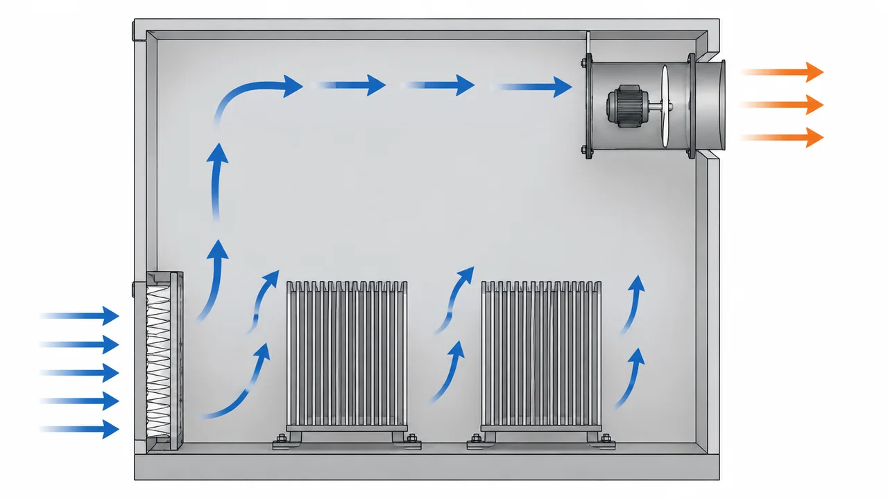
Conceptual airflow section: air enters through the filter and exits along the fan axis. Supporting hardware and guards are omitted for clarity; this is not an installation drawing.
Use the Correct Pressure Basis and Stable Operating Range
Confirm whether the manufacturer’s curve shows fan static pressure or total pressure. Give the supplier the actual inlet and outlet arrangement so it can reconcile the project requirement with the published test configuration. Comparing unlike pressure definitions can make a marginal fan appear adequate.
Also request confirmation that all intended operating points lie within the manufacturer’s recommended stable range. Do not rely on a single point close to a curve’s pressure peak. Greenheck’s vane-axial application guidance describes how excessive resistance can lead to stall and unstable operation in that fan class.
If pressure data are missing, treat selection as provisional. Obtain component data, measure a representative assembly or arrange a sample test. A useful shortlist from the Yian axial fan range is the beginning of this process, not evidence that a particular model meets the duty.
4. Match the Motor, Controls and Environment
Specify the exact available supply, including voltage, frequency and phase. Ask for the matching model suffix and its electrical documentation. Similar fan frames can contain different motors; a family-level listing should not be read as permission to connect every version to every listed voltage.
For fixed-duty equipment, an AC external rotor axial fan may be a candidate. For changing demand, an EC external rotor fan may offer relevant control options. Confirm the exact model’s input signal, speed range and feedback facilities. The existing AC versus EC fan comparison covers the broader motor-choice tradeoffs.
Request a wiring diagram and an agreed sequence of operation: what starts the fan, what sets demand, and what happens if the sensor or control signal fails. Do not assume a generic dimmer, frequency drive or PWM controller is compatible. Have the supplier identify approved accessories and protection requirements.
Compare Energy at the Actual Duty
Ask for electrical input power at the normal and peak duty points. If a machine spends most of its time below peak load, a single full-speed power figure is a poor basis for estimating operating cost.
As an illustrative purchasing calculation, a verified 0.10 kW difference maintained for 6,000 operating hours represents 600 kWh per year. Multiply by your electricity tariff, then compare the result with the installed cost difference. This example is not a promised saving from any motor technology; use the proposed models’ measured or documented duty-specific inputs.
Make Environmental Suitability a Written Requirement
Provide both ambient temperature and air-stream temperature, expected operating hours, humidity, condensation exposure and contaminants. Ask the supplier to confirm materials, bearing suitability, permitted orientation and service requirements against that information.
Identify required ingress protection for the complete assembly. A protected motor does not, by itself, establish the protection of cabinet openings, connectors or the finished equipment. For flammable gases, combustible dust, corrosive process air or unusually hot exhaust, obtain an application-specific assessment and the exact required documentation before accepting a general ventilation fan. Where the atmosphere itself is explosive, the marking and certificate route is set out in what an ATEX rating means.
For noise-sensitive equipment, define where noise will be assessed and under what operating conditions. Request comparable acoustic data, including whether it is sound pressure or sound power. Avoid accepting a lower catalog decibel number without knowing how it was measured.
5. Review the Installation Before Ordering
Check the whole assembly against the mechanical drawing: frame dimensions, flange, mounting holes, motor projection, terminal access and guard clearance. Specify the required airflow direction explicitly. Include the space needed to remove the fan and replace filters after the surrounding equipment has been built.
The mounting must support the fan as intended by its manufacturer without distorting the housing. Review adjacent panels, duct loads and vibration treatment with the equipment designer. Use the supplied mounting and tightening instructions; there is no universal bolt arrangement or clearance suitable for every industrial axial fan.
Nearby walls, abrupt transitions and bends can change performance. Greenheck’s discussion of system effect explains why the laboratory curve may not predict an obstructed installation directly. Send the supplier a layout showing the inlet and discharge surroundings, rather than only a mounting-hole sketch.
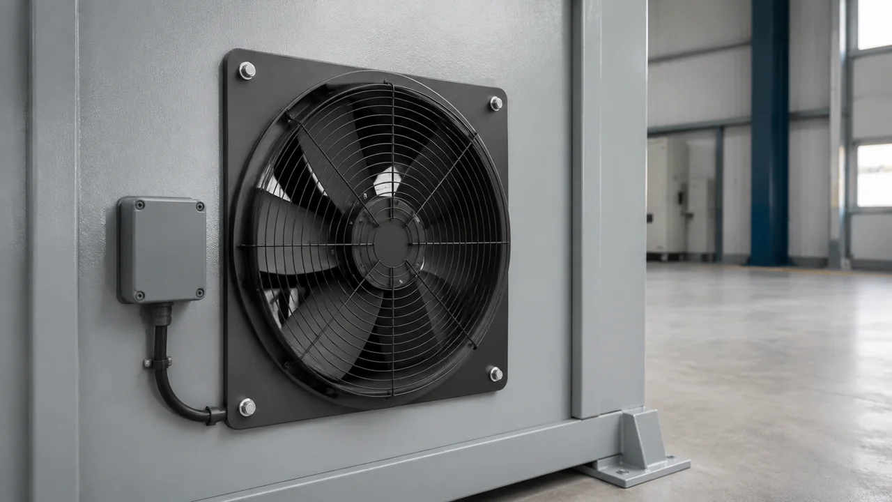
Generated mounting illustration. Confirm the actual flange, guards and clearances against the selected model’s drawing.
Trace the air from intake to exhaust. Keep hot discharge from returning immediately to the inlet, and avoid a short path that bypasses the components needing cooling. Oriental Motor’s installation guidance emphasizes limiting obstruction, stagnant zones and short airflow paths.
For a filtered cabinet, the illustrated low inlet and separated high exhaust are one possible arrangement, not a mandatory layout. Choose positions around the actual heat sources, contamination strategy and service access. The air path must work with the doors and covers in their normal operating positions.
6. Validate the Sample and Send a Complete Selection Request
Agree on an acceptance plan before placing a production order. Record the model, supply, controller settings, filter condition and ambient temperature during testing so the result can be reproduced. Test the complete air path with its intended guards, panels and accessories installed.
Confirm the supplied assembly. Check the nameplate, drawing revision, rotation and airflow direction against the order and manufacturer’s instructions.
Measure delivered performance. Use a suitable airflow or pressure measurement method agreed with the supplier. A single air-speed reading at one point on a grille may not represent the total flow.
Verify the thermal result. Run representative worst-case loads to an agreed stable condition and check critical component temperatures as well as bulk exhaust temperature.
Check the operating envelope. Validate normal and limiting resistance conditions using an agreed test method, including reduced demand where applicable.
Check power, sound and vibration. Compare observations with documented acceptance limits and investigate unexpected behavior.
Verify controls and fault response. Test the approved alarm and interlock functions using the manufacturer’s procedure; do not improvise a rotor-blocking test.
Keep unresolved findings in a selection record. For example, a fan can meet airflow yet fail a local component-temperature limit because air bypasses the component. That finding calls for a flow-path review, rather than automatically ordering a larger fan.
Your supplier request should contain the airflow-pressure duty points, heat-load assumptions, supply, control sequence, layout drawing, environment, acoustic requirements and intended operating hours. Ask for the exact model, current curve, electrical drawing, dimensions and written application confirmation.
Can I Replace an Industrial Axial Fan With One of the Same Diameter?
Diameter alone does not establish equivalence. Compare delivered airflow at pressure, power supply, speed, air direction, mounting envelope and environmental suitability. Ask for an approved replacement cross-reference or evaluate the new model against the original duty specification.
How Do I Convert CFM to m³/h?
Multiply CFM by approximately 1.699 to obtain m³/h. For example, 500 CFM is about 850 m³/h. This converts volume-flow units only; it does not correct for air density or turn a free-air rating into an installed-flow rating.
Will Two Axial Fans in Parallel Double the Airflow?
Do not assume so. The result depends on the combined fan characteristic and the system curve. Ask the supplier to evaluate the arrangement, fan interaction and the case where one unit stops. Specify required airflow during a failure if redundancy is part of the design.
Can a Larger Fan Cool Equipment Below Ambient Temperature?
An ordinary ventilation fan does not refrigerate incoming air. It may reduce the temperature rise above ambient, but below-ambient operation requires a suitable cooling process. Establish the hottest inlet-air condition before relying on ventilation.
Should I Select Only for Maximum Production Load?
Cover the peak requirement, but also evaluate normal and minimum load. Check whether the proposed controls maintain acceptable temperature and airflow at lower demand, and whether the operating points remain within the approved range. Use the expected operating profile when comparing energy cost.
A symptom-first guide to an exhaust fan not working: five failure patterns, power, control and capacitor checks, bearing faults, air-path blockages, and how to match a replacement fan.
Industrial exhaust fan noise has three distinct families - aerodynamic, mechanical and electromagnetic - and each needs a different fix. This guide gives a five-step field diagnosis, then covers source-first remedies: speed reduction, balancing, bearings, vibration isolation, silencers and placement, with the airflow trade-offs made explicit.
A practical guide to selecting and replacing a cooling fan for welding machine enclosures: heat sources, airflow path, fan specs, five common failures, and a step-by-step workshop swap.