EC Plug Fan for AHU and HVAC: What It Is and Why Engineers Specify It
Published: Author: Rachel
A belt-driven centrifugal blower has powered air handling units for decades, and it still works. What changed is not the airflow physics — it is what engineers are now allowed to leave out: the belts, the pulleys, the scroll housing, the motor base, and the separate variable frequency drive. What replaces all of it is one assembly that bolts into the plenum and takes its speed command from the building management system.
That assembly is an EC plug fan. This guide covers what the term means, why the AHU is where it became the default, how the control signal is wired and what happens when it disappears, which selection parameters decide part-load behaviour, and what a real retrofit of a belt-driven unit has to survive on site. It is written for HVAC engineers, AHU manufacturers and procurement teams who must defend a selection against a pressure budget and a commissioning deadline.
What an EC Plug Fan Actually Is
Three separate ideas sit inside one product name.
Electronic Commutation in Plain Terms
An EC motor is a brushless DC motor that accepts AC mains. Inside the housing, a controller rectifies incoming AC to DC and switches that DC through the stator windings in sequence, timed by rotor position feedback rather than by brushes or slip. Because the controller always knows where the rotor is, it matches current to load instead of running at whatever speed the supply frequency and slip happen to produce. Two consequences matter: speed becomes a software value rather than a grid-derived one, and motor losses do not rise as steeply at reduced speed. The drive electronics live inside the fan, so there is no separate inverter cabinet to buy, mount, wire and cool.
The External-Rotor Motor
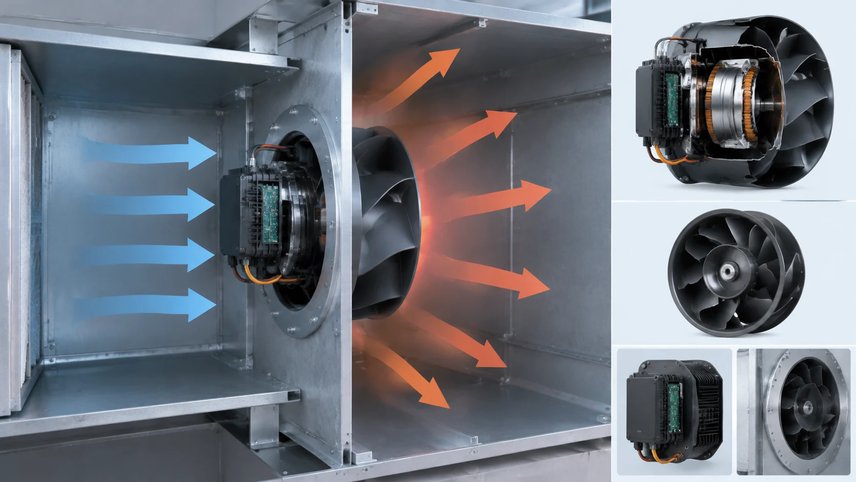
In an external-rotor design the stator is fixed to a shaft that forms part of the fan structure, and the rotor is the rotating outer part. The impeller mounts straight onto that rotor, so impeller and motor become one rotating body: no coupling, no belt run, no separate bearing pedestal in the airstream. For the AHU designer that means compactness and a shorter mechanical chain — fewer alignment tolerances, less vibration excitation, fewer wear items to schedule. The motor also shares the fan’s thermal environment, so insulation class, bearing type and the stated ambient limit must be checked against the airstream temperature, not the plant room.
Why “Plug” Means No Volute
A conventional centrifugal fan converts impeller velocity into static pressure inside a scroll casing before discharging through a rectangular outlet. A plug fan deletes the scroll and discharges radially in all directions into the chamber it sits in; the enclosure — for an AHU, the fan-section plenum — performs the pressure recovery the scroll used to do. That explains the packaging, the airflow pattern and the discharge-direction freedom, and it transfers responsibility: the plenum is now part of the aerodynamic circuit.
Why the AHU Is Where Plug Fans Became Standard
The plug-fan idea is old; pairing it with integrated EC control is what is new.
The Plenum Becomes the Housing
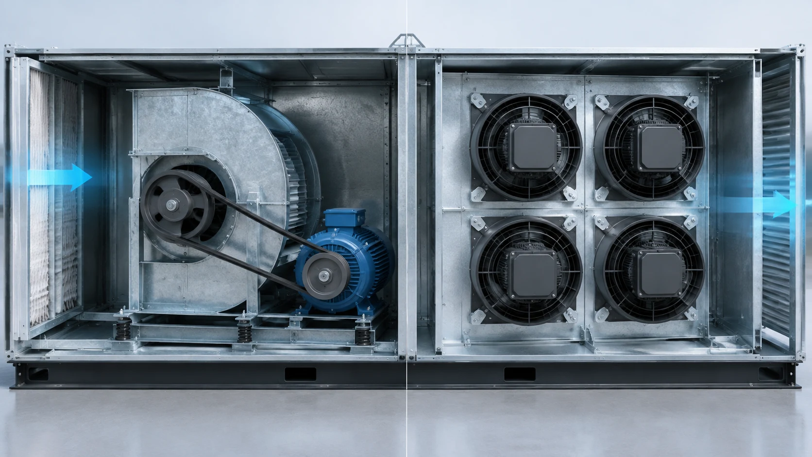
An air handling unit already contains a fan section with a pressure boundary, which is exactly what a plug fan needs. The impeller and motor sit on a bulkhead inside space that had to exist anyway, and removing the scroll and belt guard removes the long rectangular discharge transition that used to stretch the fan section out. Shorter fan sections cut both quotation cost and floor space, which is why AHU manufacturers adopted the change early.
Uniform Discharge Across the Coil
A volute discharges a concentrated, directional jet, which leaves high velocity in part of the plenum and near-still air in the corners; downstream, the coil works hard in one band and does nothing in another. A radial exit spreads the same air over a much wider area before it reaches the coil. The gain is not more airflow but better use of it: even face velocity improves heat transfer per unit of air and delays the point where one band of a filter loads far ahead of the rest.
Why Retrofit Projects Reached for Them First
On a new unit the argument is cost and packaging. On an existing AHU it is stronger, because the alternative to a power-train swap is replacing the asset. A refurbishment replaces the blower, motor base, belt guard and scroll with a plug fan assembly on a new bulkhead; casing, coil, filters, dampers and ductwork stay put. Belt dust also disappears, removing a contamination source that counts in healthcare and pharmaceutical work, and a set of smaller fans can carry spare capacity so that one failure degrades performance instead of stopping the unit.
EC Plug Fan vs AC Centrifugal Fan: Where the Difference Shows Up
Most procurement spreadsheets are built around this comparison, and it is easy to get wrong by comparing the wrong two things. The question is really about drive trains and part-load behaviour — the centrifugal impeller itself is present in both cases.
Two Different Drive Trains
The classic AHU blower is a double-inlet centrifugal impeller inside a scroll, driven by an external induction motor through pulleys and belts. Speed is set mechanically by pulley ratio, and airflow is trimmed with a damper or by fitting a VFD. Losses accumulate along that chain: belt friction, pulley wear, misalignment, and the energy a slip-driven motor dissipates when loaded below its design point. A plug fan shortens the chain to motor and impeller on a common rotating body, with nothing to tension, align or replace on a schedule. The savings come from removing those mechanical losses and controlling speed electronically, not from any single headline efficiency figure, which varies with motor size, impeller design and working point.
Item
Belt-driven AC centrifugal blower
AC blower with external VFD
EC plug fan
Drive
Belts and pulleys, external motor
Belts and pulleys, external motor plus VFD
Direct-drive external-rotor motor
Speed control
Pulley ratio, fixed
VFD, external cabinet
Built-in controller, signal-driven
Part-load power
Stays high while a damper throttles
Falls with the cube of speed
Falls with the cube of speed
Maintenance items
Belts, pulleys, bearings, alignment
Belts, pulleys, bearings, VFD
Impeller cleaning and bearings
Redundancy
Single machine
Single machine
Array can be sized for n+1
Space taken
Long fan section plus belt guard clearance
Long fan section plus panel space
Compact, plenum-mounted
Typical fit
Constant-volume units, price-driven tenders
Variable-volume upgrades without a fan swap
VAV units, fan arrays, hygiene-sensitive duty
Part-Load Behaviour Is the Real Divider
Air handling units rarely run at design airflow. Occupancy, solar gain and internal loads all vary, yet a fixed-speed fan delivers design airflow all day. The relationship that matters is the fan law: power varies roughly with the cube of rotational speed, so a modest speed reduction produces a much larger reduction in input power. A damper cannot exploit that relationship. It adds resistance to reduce flow, increasing the pressure the fan must generate while the fan keeps drawing roughly the same power, and often more as the operating point moves back up the curve. The meaningful comparison is therefore against a damper-controlled unit, not against a fan that already varies its speed.
Why a VFD on an AC Blower Is Not Equivalent
A modern VFD on a well-matched induction motor is a legitimate solution and delivers most of the airflow control benefit. What it does not deliver is the packaging and maintenance simplification: the belt and pulley set remains, the VFD cabinet still needs mounting, cooling and protection settings, and it must be commissioned to the motor. The failure surface is larger, and a VFD fault trips the whole fan. Where a VFD already exists and works, replacing it may not be the highest-return measure. Where the belt drive is near the end of its service life, the two options are much closer in cost and the packaging advantage becomes decisive. For the motor-technology comparison in isolation, see our guide to AC fans versus EC fans.
When the Belt-Driven Unit Still Makes Sense
There are real cases where a belt-driven blower is correct. If the airstream is hot enough to threaten integrated electronics, if the process gas is corrosive, if the site suffers severe voltage disturbances, or if the required static pressure exceeds what available plug-fan sizes can reach, the mechanical drive remains defensible precisely because it keeps sensitive parts out of the airstream. EC units win in the clean, moderate-temperature, variable-airflow duty that makes up most of a building’s fan energy, and should not be specified by reflex outside that envelope.
How the Fan Is Commanded: 0-10V, 4-20mA, PWM and Modbus
Most delays on EC fan orders do not come from the fan, but from a control question nobody asked until the airflow figure was already fixed.
What Each Signal Actually Carries
An integrated controller exposes a small terminal set rather than a power circuit: a speed setpoint input, a reference supply, a common, status feedback, and often a two-wire serial pair. The setpoint input is the one that must match your BMS, and the flavours are not interchangeable.
Signal
What it is for
Strengths
Watch out for
0–10 V DC
Analog speed setpoint from a panel or AHU controller
Simple, widely supported, easy to scale
Voltage drop and noise on long runs; the meaning of 0 V differs between models
4–20 mA
Analog setpoint where cable runs are long or noisy
Immune to loop resistance; live zero lets the controller detect a broken wire
Needs defined scaling and often an input resistor; confirm before ordering
PWM
Speed setpoint from a controller that outputs a duty cycle
Uses plain digital outputs; good for simple open-loop demands
Frequency and duty conventions vary; verify compatibility with the model
RS485 / Modbus RTU
Speed command plus readback of speed, current, temperature and faults
Bidirectional, multi-drop, supports alarms and staging logic
Needs an agreed register map, baud and parity, correct termination and addressing
Open Loop and Closed Loop Are Different Purchases
In open loop the controller writes a setpoint and the fan obeys it, which is all a variable-volume unit needs when the AHU controller already computes the required speed. In closed loop the fan compares a measured value — static pressure, airflow or temperature — against a setpoint and adjusts its own speed to hold it. That is useful where duct resistance changes over time, for instance as filters load, because the fan compensates without the BMS being re-tuned. Not every model and firmware build supports it, so it should be specified deliberately.
What Happens When the Signal Drops
This is the question competitors rarely answer, and where a retrofit can go wrong quietly. When the setpoint wire is cut, the serial link fails, or the controller output falls to zero, does the fan stop, hold its last speed, or run to a configured fallback speed? The answer is a configuration item, not a fixed rule, and it must be decided against the consequence. A supply fan serving occupied space that stops abruptly on a comms fault can trip an airflow alarm and shut the unit down; one that ramps to a fallback keeps the space ventilated while the fault is investigated. Write the chosen behaviour into the commissioning sheet and test it by actually pulling the wire. Confirm the available options with the manufacturer before the order, because changing them later may require a parameter tool and a site visit.
The Selection Parameters That Actually Decide the Fan
Once application and control interface are settled, selection reduces to a short list of parameters that carry real information.
The Airflow-Static Pressure Curve
The only honest description of a fan’s performance is its airflow-versus-static-pressure curve. Any single airflow figure is a point on that curve at a stated pressure and means nothing without the pressure. Plot the system resistance curve — filters, coil, dampers, ductwork, grilles — and choose the fan whose curve crosses it at the required airflow, comfortably away from the stall region at the left-hand end and away from the steep right-hand end where small pressure changes cause large flow changes. Ask for the curve at the actual operating speed and for the impeller diameter you are offered.
Speed, Power and Starting Current
Rotational speed determines tip speed, which drives noise, bearing load and mechanical stress. Confirm the maximum allowable speed, and confirm the fan is not being specified at a speed it can only reach with a heavier impeller than the one quoted. Shaft input power and motor input power are different numbers — the gap is controller and motor loss — and supply capacity depends on the second. Starting behaviour matters in retrofit work where the supply is not being upgraded, so confirm inrush characteristics and whether soft-start is built in.
IP Rating and the Conditions Inside the Plenum
An AHU plenum is a wet, dusty, sometimes condensate-laden environment, and it is not the plant room. The enclosure rating has to match the actual conditions: humidity from a humidifier section, water carry-over from a cooling coil, fine dust from unclassified outdoor air. A rating suitable for a dry plant room may be inadequate a metre downstream of a spray humidifier. Ask what is offered on the motor enclosure and the controller enclosure separately, and whether the airstream temperature at the fan location has been accounted for. Both answers should be in writing.
Noise, and Where It Is Measured
Sound power is more useful than sound pressure because it is independent of distance and room. Where only sound pressure is quoted, confirm the measuring distance and the operating point, because noise at full speed is not what the building experiences at part load. In fan arrays, the combined level of several modules is not simply the sum of the individual levels. Confirm whether the figure includes motor, controller and casing, and whether it is free-field or ducted.
Sizing Against the System, Not the Headline Number
The most common selection error is not choosing the wrong fan size. It is choosing the right fan at the wrong pressure.
The Working Point Versus the Free-Air Rating
A fan’s maximum airflow occurs at zero static pressure, in free air — a condition that exists in a test rig and nowhere else. Your system always presents resistance, so delivered airflow will be lower than the catalogue maximum. If a quotation leads with a maximum airflow figure and no corresponding pressure, that figure describes nothing about your installation. Size the fan at the system’s real resistance at design airflow, then check the same fan still behaves sensibly when resistance rises as filters load.
Filter Loading and the Dirty-Filter Allowance
Filters load progressively and resistance climbs with them. A system designed at dirty-filter resistance will over-deliver when the filters are new and may need trimming; one designed at clean-filter resistance will under-deliver for most of its service life. The usual compromise is to select at an intermediate resistance with some allowance above it, and let the control system hold airflow as resistance varies. If the fan is commanded in open loop, the allowance has to be built into the selection explicitly, or the building will get progressively less air and nobody will know why.
One Large Fan or a Fan Wall
A fan array replaces one large fan with several smaller modules on a common bulkhead. Total airflow can be matched, but the operational characteristics change in useful ways.
Consideration
One large plug fan
Fan wall of smaller modules
Failure behaviour
Airflow stops with the fan
Remaining modules can be staged to compensate
Service access
Large lifting and handling task
Modules handled individually
Part-load efficiency
One fan turning down
Modules staged on and off; fewer running at higher efficiency
Bulkhead requirement
One large cutout, high local loads
Uniform panel, more cutouts, tighter build tolerance
Noise character
Concentrated at one impeller
Spread across modules; combined level needs field measurement
Best fit
Small to medium units, single duty point
Critical duty, high airflow, redundancy requirements
An array is not automatically better. It adds cutouts, wiring and staging logic, and it needs a bulkhead stiff enough to carry the modules without drumming. It earns its cost where downtime is expensive or airflow is large enough for modularity to pay for itself.
Retrofitting a Belt-Driven AHU: The Landing Sequence
A retrofit is a construction project inside a working air handling unit, and the sequence matters as much as the fan choice.
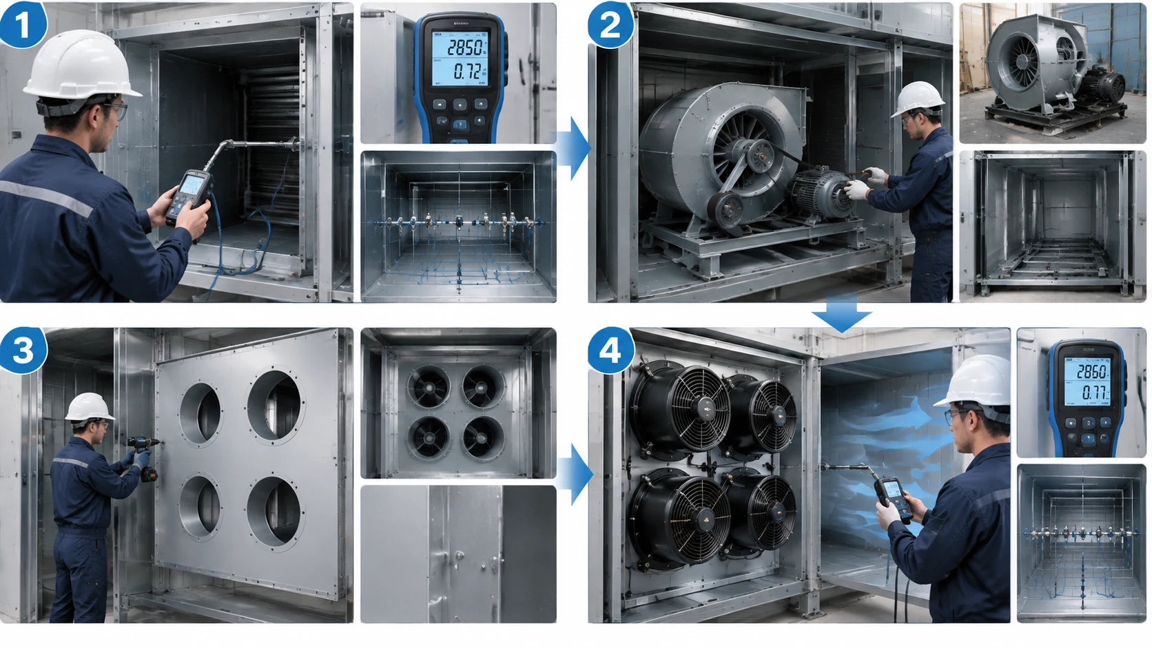
Step 1 — Measure the Real Duty, Not the Nameplate
Before anything is ordered, establish what the unit is actually doing: supply airflow if it can be measured, static pressure across the fan and the coil, filter differential pressure, damper positions, motor current, and the real operating-hours profile. Original design documents are a starting point, but units get modified, ducts get added and dampers get left partly closed, so the as-found condition is the only reliable baseline. A fan selected from the nameplate alone will be oversized or undersized by exactly the amount someone changed the system years ago.
Step 2 — Strip the Blower, Motor Base and Scroll
Remove the existing impeller, scroll, belt guard, motor base and pulleys. This is also the point to inspect what belt dust has been doing to the coil and filter section, and to check the fan-section floor and walls for corrosion where condensate has collected behind the belt guard. Removing the scroll frees the space that makes an array possible, but it also changes the load paths in the casing, so check the panel for stiffening before cutting anything.
Step 3 — Build the Bulkhead or Fan Wall
The plug fan needs a mounting boundary that separates the suction side of the plenum from the discharge side, otherwise air simply recirculates around the impeller. This bulkhead is a structural and sealing item, not a trim panel: it carries the fan loads, resists the pressure differential, and is sealed at its perimeter and around every cable entry. Position the cutouts so the impeller has clean, unobstructed approach on the suction side; a fan starved by a nearby return bend or a protruding filter frame will never deliver its curve.
Step 4 — Re-commission and Verify Airflow
After connection and control integration, verify the actual outcome rather than the expected one. Measure airflow with a recognised traverse method, record static pressures across coil and filters, confirm the fan reaches design speed and current, and check the control loop holds setpoint when load changes. Then test fault behaviour deliberately: pull the setpoint signal and confirm the fan does what the design intended.
What to Do With the Existing VFD
If the old unit had a VFD driving the induction motor, it becomes redundant once the fan has its own controller. It can be removed, left in place but isolated, or occasionally retained to drive another fan in the plant room. What it must not be is left connected between the supply and the EC fan, because the fan expects a clean mains supply and an external VFD is not designed to feed it.
What Breaks a Retrofit That Looked Fine on Paper
Three problems recur in AHU conversions.
Airflow Measurement Points That Never Existed
The old fan had a rectangular outlet in a known location, and the traverse plane that goes with it. A plug fan discharges radially into the plenum, which is better for the coil but destroys the convenient measurement plane. Without a defined traverse plane the airflow cannot be verified, the control loop cannot be validated, and any later complaint becomes an argument. Plan the measurement location as part of the bulkhead design, and if no suitable plane exists in the existing casing, say so before the work starts.
Damper and Setpoint Logic
Units converted from constant volume often carry control logic built around a damper. If the damper remains in the airflow while the fan is now modulated, the two control actions fight each other: the fan increases speed to hold pressure while the damper closes to hold flow, and the system hunts. The damper should be driven fully open and locked, or removed, and the sequence rewritten to modulate the fan alone. The same applies to any old pressure setpoint tuned for a fixed-speed fan; it must be re-established from design airflow.
Access, Drainage and Service Clearance
A fan array on a bulkhead needs a service side. If the modules are mounted so their cabling and fixings face the coil or a humidifier section, every future inspection becomes a partial strip-down, so check that cable entries, earth bonding points, isolators and fixings are all reachable from the access side. Drainage is the other quiet failure: condensate that used to run down the casing and leave can now collect on a horizontal bulkhead, corroding fixings and eventually reaching the motor. Add drainage or a fall to the existing condensate route as part of the build.
Where a Plug Fan Is the Wrong Answer
These fans are not a universal replacement.
High-Temperature and Corrosive Airstreams
Because the motor and its controller sit in the airstream, temperature and chemistry are direct constraints. In high-temperature process exhaust, ovens, dryers or kilns, the electronics may exceed their allowable ambient no matter how well the impeller is rated. In chemically aggressive airstreams, integrated electronics are more vulnerable than a bare motor placed outside the duct, and coatings only delay attack rather than preventing it. For these duties a conventionally driven fan with the motor isolated from the airstream remains the safer architecture — a case where a less advanced solution is the correct engineering answer.
Dirty Power and Grid Quality
Integrated electronics are more sensitive to voltage disturbance than a plain induction motor. On sites with frequent severe swells, sags or harmonics, the controller is the component most likely to be damaged, and a failed controller on an integrated fan often means replacing the whole assembly rather than one cheap part. Where power quality is poor, either add protection at the distribution level or reconsider the fan type.
Spare-Parts Strategy on a Remote Site
On a remote or unmanned site the maintenance profile shifts. A belt-driven machine can often be kept running with locally available belts and bearings, whereas an EC fan with a failed controller may need a factory replacement and a lead time. For a critical remote installation the sensible answer is usually a stocked spare module rather than a different fan type — and that decision belongs in the procurement plan, not in the maintenance reaction.
The Datasheet Questions Worth Asking Before You Order
Two quotations for “an EC fan” at nominally the same duty can be very different products. The difference shows up in what the documents do not say.
Read the Curve, Not the Header
Look for a curve with both axes and a stated operating speed. Check that it covers your working point and that the point sits in a stable region rather than near stall or the steep end. Check whether the curve is for the impeller you are being offered, at the speed you will actually run. If the submission contains a single airflow number and no pressure, ask for the rest before comparing prices.
What the Product Label Does Not Say
Three items are frequently absent from the headline specification and decisive in service: the motor enclosure rating and the controller rating, the maximum airstream temperature at the fan, and the control interfaces actually supported by that specific model and firmware. All three should be confirmed in writing for the exact model offered, not inferred from a family datasheet. Bearing type belongs on the same list: regreaseable bearings need a planned maintenance route, sealed-for-life bearings define the service interval instead.
Five Questions to Send the Manufacturer
What is the airflow and static pressure at my duty, and what speed does that correspond to?
Which control signals does this exact model support, and what does it do if the setpoint signal is lost?
What is the protection rating of the motor and of the controller, and what airstream temperature are they rated for?
What is the sound power level at the operating point, and how was it measured?
What are the mounting dimensions, the suction-side clearance requirement, and the maintenance access needs?
Answers to those five questions, in writing, filter out most of the risk that remains after the price comparison. Our own range of EC external-rotor fans is documented on that basis, and the same figures are available for the AC external-rotor axial range where a separate drive is preferred.
Frequently Asked Questions
What is an EC fan in an AHU?
It is a fan whose motor uses electronic commutation — a brushless DC motor with an integrated controller that accepts AC mains — mounted inside an air handling unit to move supply or return air. In an AHU it is usually supplied as a plug fan, meaning the impeller has no scroll casing and discharges directly into the unit’s plenum. Speed is commanded electronically, so airflow can follow the building’s actual demand without a separate VFD.
What is the full form of EC in HVAC?
EC stands for electronically commutated. It describes how the motor’s windings are switched: not by mechanical brushes or by the fixed frequency of the supply, but by an electronic controller that switches current according to rotor position. In HVAC writing EC is used loosely to mean “a fan with an integrated electronic speed controller”, and the full form is worth keeping in mind because it explains why these fans respond directly to a setpoint signal and hold efficiency better at reduced speed.
Is an EC plug fan the same as a centrifugal fan?
Not exactly. A plug fan uses a centrifugal impeller, usually backward-curved, but omits the scroll casing that defines a conventional centrifugal fan, discharging radially into the surrounding plenum instead. EC refers to the motor and its control, a separate choice from impeller style. So it is a centrifugal machine in aerodynamic terms and a different product in structural and control terms; an ec plug fan vs centrifugal fan evaluation is really a comparison of drive train and housing, not of impeller family. For the impeller side, see our explainer on what a centrifugal fan is.
Do EC fans need a separate VFD?
No. The speed controller is built into the fan, so it accepts a setpoint signal directly from the controller or BMS and does not require an external variable frequency drive. Wiring an EC fan through an external VFD is not a valid configuration and can damage the unit. This is one of the main practical differences from an AC blower, where a VFD is the usual way to obtain variable speed.
Can a plug fan replace a belt-driven AHU blower directly?
Usually yes, but not as a like-for-like swap. The fan assembly, mounting bulkhead and control wiring all change, so the work is a small construction project rather than a component replacement. Measure the unit’s airflow first, select a fan or array to match that duty on its pressure curve, and rewrite the control sequence to modulate the fan instead of a damper. Where existing static pressure is unusually high, check that available plug-fan sizes can reach it before committing.
What to Confirm Before You Issue the PO
Decide the fan from the duty, not the label. Measure what the unit is actually doing, select on the airflow-static-pressure curve at the real system resistance, and build in an allowance for filters loading over time. Settle the control interface before the airflow number is frozen, and write down what the fan must do when its signal disappears. Confirm protection ratings and airstream temperature limits for the exact model, not the family. Then plan the retrofit as a sequence: measure, strip, build the bulkhead, commission and verify by measurement, and test fault behaviour on purpose.
These fans are the right default for clean, moderate-temperature, variable-airflow AHU duty, and the wrong answer for very hot, chemically aggressive or power-quality-poor installations. Being clear about which case you are in is what makes the specification defensible. For adjacent selection problems, our guides to small AC centrifugal blowers, industrial axial fan selection and electrical cabinet cooling fan selection cover the cases where the answer is a different fan family.
A symptom-first guide to an exhaust fan not working: five failure patterns, power, control and capacitor checks, bearing faults, air-path blockages, and how to match a replacement fan.
Industrial exhaust fan noise has three distinct families - aerodynamic, mechanical and electromagnetic - and each needs a different fix. This guide gives a five-step field diagnosis, then covers source-first remedies: speed reduction, balancing, bearings, vibration isolation, silencers and placement, with the airflow trade-offs made explicit.
A practical guide to selecting and replacing a cooling fan for welding machine enclosures: heat sources, airflow path, fan specs, five common failures, and a step-by-step workshop swap.