What Is the Lifespan of an Axial Fan? | Complete Guide
Learn how long axial fans last, what L10 life means, which conditions shorten service life, and how inspection and maintenance reduce failures.
Read More
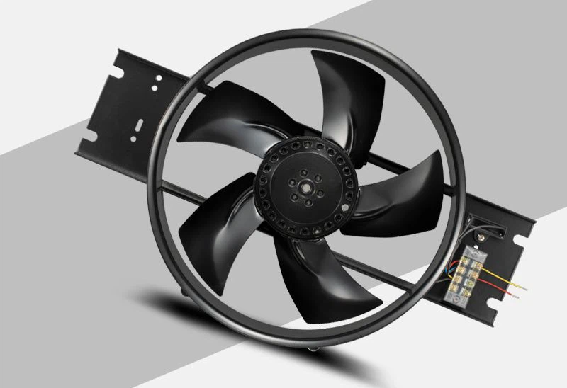
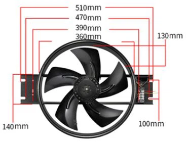
An axial fan works by rotating angled blades around a central hub. The blades create a pressure difference across the fan, draw air into the inlet, add velocity and pressure to it, and discharge it in a direction roughly parallel to the motor shaft. This straight-through airflow is why the design is called an axial fan.
The principle sounds simple, but actual performance depends on blade shape, pitch, diameter, speed, tip clearance, housing design, and the resistance of the connected system. This guide follows the air from inlet to outlet, explains the main components, and shows why a fan that moves plenty of air in open space may deliver less when installed behind a grille, coil, filter, or duct.
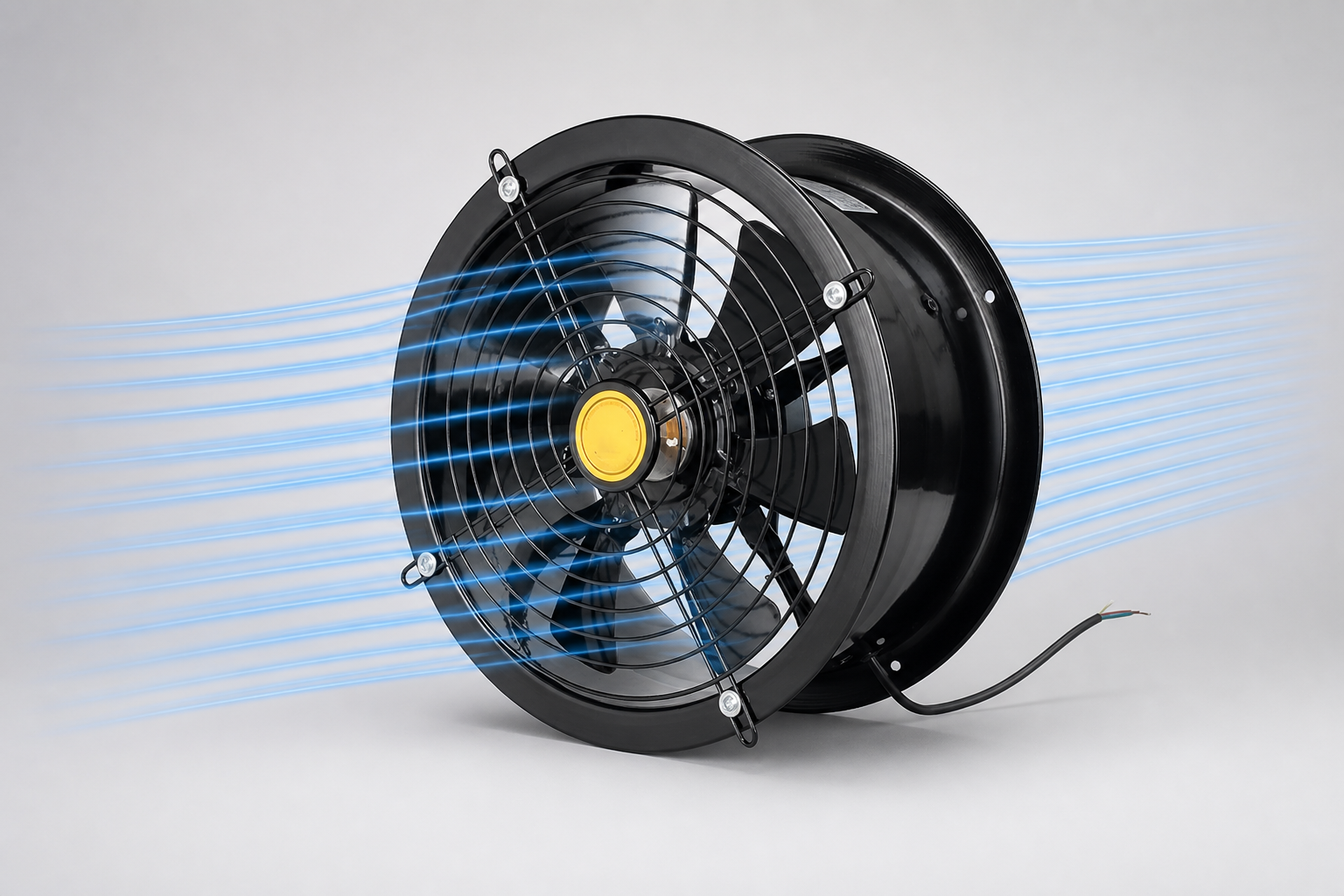
In energy terms, the path is electrical energy to mechanical rotation and then to air velocity and pressure. The fan does not create air; it establishes the pressure difference that makes air flow through the available path.
An axial-fan blade works like a rotating wing. Its curved profile and angle of attack make the air travel differently over its two surfaces, creating an aerodynamic force. One component of that force acts in the axial direction and pushes air through the fan. The opposite reaction appears as torque on the motor shaft.
The blade also gives the discharge air a tangential component, so the flow often follows a shallow helical path rather than moving in perfectly straight lines. In a vane-axial design, stationary guide vanes downstream of the impeller remove part of this swirl. Redirecting the flow can convert otherwise wasted rotational energy into useful pressure.
These variables must be designed as a system. More blades or more pitch do not automatically produce a better fan. The motor, impeller, housing, operating point, and acoustic limits all need to match.
| Component | Function | Why it matters |
|---|---|---|
| Motor | Provides torque and rotational speed | Determines compatible power supply, control method, heat, and part-load behavior |
| Hub and impeller | Support the blades and transfer motor torque to the air | Influence airflow, pressure, balance, and efficiency |
| Blades | Create aerodynamic force and accelerate air | Pitch, profile, count, and material shape the fan curve |
| Frame or casing | Supports the assembly and guides the airstream | Controls tip clearance and installation geometry |
| Guard | Reduces access to moving blades | Improves safety but adds resistance if too restrictive or dirty |
| Guide vanes | Straighten discharge swirl in some designs | Can improve pressure recovery and flow quality |
| Bearings and supports | Keep the rotor aligned during operation | Affect vibration, noise, reliability, and service life |
External-rotor construction places the rotating motor shell around the stator and can create a compact motor-and-impeller package. Yian Electric’s AC external rotor axial fan is one example of this arrangement. Electronically commutated versions add integrated motor electronics; see the EC external rotor exhaust fan for a controllable alternative.
Airflow is the volume of air moved per unit of time, commonly stated in m³/h or CFM. Static pressure represents the fan’s ability to overcome resistance. Duct friction, bends, filters, coils, louvers, guards, and small openings all add resistance.
A fan does not deliver one fixed airflow under every condition. Its operating point occurs where the fan curve intersects the system curve. With little resistance, an axial fan may move a high volume of air. As resistance rises, its delivered airflow usually falls. This is why a free-air rating cannot predict performance inside a restrictive machine or duct system.
Select an axial fan at the required airflow and pressure together—not by diameter, RPM, or free-air volume alone.
For a model-level selection process, use the small axial fan selection guide. When comparing published data, independently certified ratings can improve confidence; the AMCA Certified Ratings Program identifies axial fans certified for stated performance attributes.
| Type | Flow arrangement | Typical strength |
|---|---|---|
| Propeller or panel fan | Open or shallow-frame impeller | High airflow where resistance is low |
| Tube-axial fan | Impeller inside a cylindrical housing | Controlled inline flow through short ducts |
| Vane-axial fan | Tube-axial rotor plus guide vanes | Better swirl control and higher pressure recovery |
| Variable-pitch axial fan | Blade angle can be selected or adjusted | Matching performance to changing duty requirements |
All four use the same core mechanism: rotating blades add energy while the principal airflow remains axial. The housing, vanes, and pitch arrangement determine how effectively that energy becomes useful flow and pressure. The broader axial fans guide covers common designs and industrial applications in more detail.
For the same fan and approximately similar air density, the fan laws provide a useful first estimate: airflow changes roughly in proportion to speed, pressure roughly with the square of speed, and power roughly with the cube of speed. These relationships explain why variable-speed control can be valuable, but they are approximations. Motor efficiency, controller losses, Reynolds-number effects, and changes in the system curve can alter real results.
AC, DC, and EC motors can all be used in axial fans, but their compatible controls differ. The AC vs DC axial fan comparison explains supply and signal considerations. Always use the control method approved for the exact motor; an unsuitable controller can cause overheating, poor torque, electrical noise, or unstable operation.
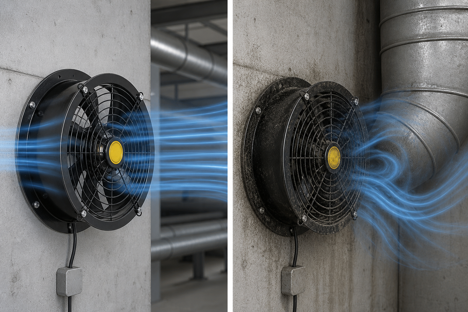
Laboratory fan curves are measured under defined test conditions. A real installation can disturb the inlet or outlet and create a system effect that reduces delivered performance. The U.S. Department of Energy’s fan-system sourcebook discusses fan curves, system curves, controls, and system effects as parts of whole-system performance.
An axial fan keeps the main flow approximately parallel to the shaft. A centrifugal fan draws air into the impeller eye and sends it radially outward, normally turning the flow about 90 degrees before discharge. Axial designs are commonly favored for high volume at low or moderate resistance, while centrifugal designs are often chosen when the system requires more static pressure.
Neither principle is universally better. The correct choice follows the duty point, available space, air cleanliness, sound limits, efficiency target, and installation geometry. Read what a centrifugal fan is for a detailed explanation of the alternative airflow path.
It does both as part of one continuous flow. The rotating impeller creates lower pressure at the inlet and higher pressure at the outlet, so air enters one side and leaves the other.
The blades are arranged to produce a dominant force along the rotation axis. The discharge can contain swirl, but its main velocity component is axial.
Simply reversing motor rotation does not guarantee equal reverse performance. Most blades and housings are optimized for one rotation and flow direction. Use a purpose-designed reversible fan when bidirectional duty is required.
The filter adds pressure resistance, and that resistance increases as it loads with dust. The operating point moves along the fan curve to a lower airflow unless speed or system conditions change.
Stall occurs when airflow no longer follows the blade surface as intended, often because of excessive system resistance, disturbed inlet flow, or unsuitable blade loading. It can produce unstable flow, noise, vibration, and reduced performance.
Yes, when its fan curve covers the required airflow and total resistance. Tube-axial and vane-axial designs are built for inline use, but long or restrictive duct systems may favor a higher-pressure fan type.
An axial fan works by using rotating, angled blades to create a pressure difference and accelerate air mainly along the motor-shaft axis. Blade geometry supplies the aerodynamic force; the motor supplies torque; and the frame, casing, guide vanes, and installation determine how much of that energy becomes useful airflow and pressure.
For reliable selection, define both airflow and system resistance, check the complete fan curve, and account for inlet and outlet conditions. If you need help matching an axial fan to an enclosure, condenser, ventilation opening, or duct system, send the operating point and installation details through the Yian Electric contact page.